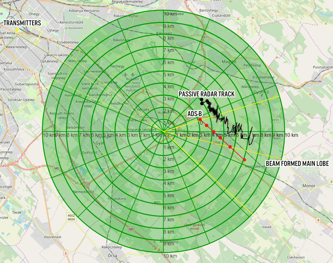
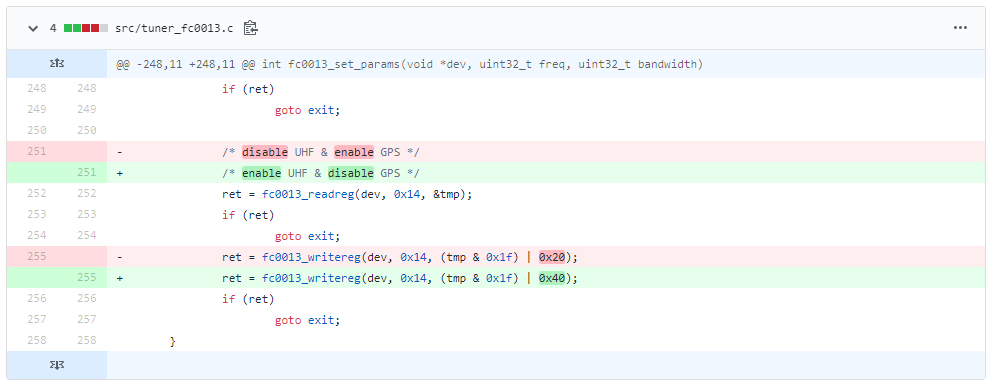
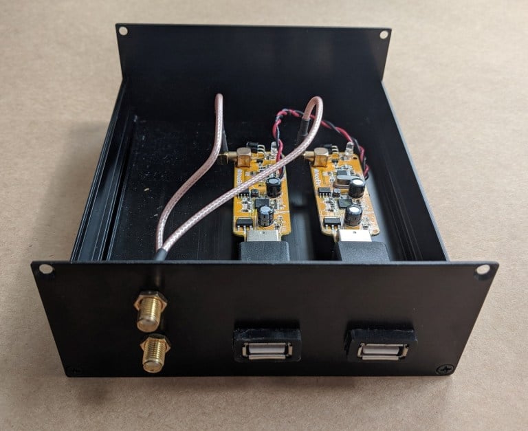
KerberosSDR is our experimental 4-Tuner Coherent RTL-SDR product made in collaboration with Othernet. It can be used for applications such as radio direction finding and passive radar. Currently it's available for US$149 on the Othernet store.
The RDF Mapper software allows you to upload bearings from multiple devices distributed around a city to a public RDF server, and view all the bearings on any internet connected PC. This can allow you to quickly triangulate the location of a transmitter.
Normally you would use RDFMapper combined with an RDF42 to upload bearings, but we've written a simple script that can be used to upload bearings generated by a KerberosSDR onto the server. The RDFMapper software can then be used to visualize those bearings.
The script is based on Python, and can run directly on the Pi 3/4 or Tinkerboard that is running the KerberosSDR, or on another PC that can see the KerberosSDR bearing server if you prefer.
Instructions are available on the GitHub page. Simply set unique station names for each of your distributed units, entry your lat/lon and fixed direction bearing. Then on the RDF Mapper software open the 'Web upload/download' tab and add the unique station ID name. All the other tabs for connecting to a GPS and serial port can be ignored, as those are used for the RDF42.
This script will only work for stationary KerberosSDR units as the lat/lon is fixed. If you want to try radio direction finding in a vehicle, we recommend using our Android App for a better experience. If there is interest, we may also add support for the Android app to upload to an RDFMapper server for mobile bearing uploads.
Notes: RDFMapper runs on the system's default browser and it needs to run in either Chrome or Firefox to work. IE does not work. It also appears that Jonathan processes orders manually, so we just want to note that there may be a delay between payment and receiving the software.
RDF Mapper Software. Plotting bearing data from networked units.
Over on YouTube the TechMinds YouTube channel has uploaded a review of our RTL-SDR Blog L-Band patch antenna which we recently released. TechMinds tests the antenna on a STD-C Inmarsat channel with the Scytale-C decoder, and on various AERO ACARS transmissions with JAERO. Later in the video he also tests the patch antenna on Iridium reception using the Iridium Toolkit software. In all tests the patch is able to suitably receive the signal with either an RTL-SDR or Airspy SDR.
We also wanted to make a note about an additional tip regarding polarization that many people using the antenna seem to have missed. As Inmarsat signals are LHCP polarized, it is important to not only point the antenna towards the satellite, but also to rotate the antenna to match the polarization until maximum SNR is achieved. The rotation can make the difference between strong signals and nothing received at all.
RTL-SDR Active L-Band Patch Antenna For Inmarsat / Iridium / GPS
We've also recently seen a user 'Bert' who has needed to boost the signal strength as he was running the patch inside and at a location in northern Europe with poor reception of Inmarsat. To boost it he simply added a metal horn over the patch made from an old aluminum box, and also a back plate reflector. He notes that this improved his SNR on AERO 10500 from 8 - 9 dB, up to 12 - 14 dB. He also tested using the patch on a dish antenna, and found very good results too.
Aluminum Horn Added to L-Band PatchL-Band Patch Antenna on Dish
The RAPIDS cuSignal project is billed as an ecosystem that makes enabling CUDA GPU acceleration in Python easy. Scipy is a Python library that is filled with many useful digital signal processing (DSP) algorithms. The cuSignal documentation notes that in some cases you can directly port Scipy signal functions over to cuSignal allowing you to leverage GPU acceleration.
In computing, most operations are performed on the CPU (central processing unit). However, GPU's (graphical processing units) have been gaining popularity for general computing as they can perform many more operations in parallel compared to CPUs. This can be used to significantly accelerate DSP code that is commonly used with SDRs.
In particular the developers have already created a notebook containing some examples of how cuSignal can be used with RTL-SDRs to accelerate an FFT graph. There are various other DSP examples in the list of notebooks too. According to the benchmarks in the notebooks, the GPU computation times are indeed much faster. In the benchmarks they appear to be using a high end NVIDIA P100 GPU, but other NVIDIA graphics cards should also show a good speedup.
The cuSignal code is based on CUDA, so for any GPU acceleration code to work you'll need to have an NVIDIA based GPU (like a graphics card) with a Maxwell or newer core.
We note that in the future we'll be investigating how this could be used to speed up the passive radar algorithms that are used in the KerberosSDR. It may also be useful for running DSP code quickly on a $99 NVIDIA Jetson Nano single board computer.
The tutorial starts by showing you how to set up your Amazon AWS credentials and bucket on the Raspberry Pi, and how to host a simple webpage that can be accessed publicly. The second stage shows how to set up the RTL-SDR drivers and wxtoimg which is used to decode the images. Finally, the third stage shows how to create the automation scripts that automatically schedule a decode, and upload images to the AWS bucket.
Flowgraph for an automated NOAA satellite weather image station.
Atlassian Opsgenie Engineer Fahri Yardımcı has recently written up an interesting post that details how he's using Opsgenie and Amazon Transcribe to automatically create alerts when specific voice phrases are mentioned on a radio channel. For example, if the words "blue team" are heard on the radio, the system can automatically issue an alert with the spoken words to members of the blue team in an organization. Amazon Transcribe is a cloud based speech to text service and Opsgenie is a platform that is used for managing and delegating alerts from multiple IT or other computer systems.
The system works by using an RTL-SDR and the ham2mon software to scan, receive and record voice from multiple voice channels. Fahri notes that he modified ham2mon slightly in order to allow it to upload the .wav files to an AWS S3 server which then runs the Amazon Transcribe service to convert the voice into a text file.
To make an interesting use case, we have imagined this scenario: When we detect a phrase in predefined words, like “Help”, “Execute Order 66”, “North outpost is compromised”, “Eggs are boiled”, we want to create an alert in Opsgenie. Opsgenie can send notifications to users via various ways such as push notifications and calls.
Amazon Transcribe uses advanced machine learning methodologies, to convert an audio stream to a text. As mentioned before, ham2mon uploads to .wav files to S3 and a Lambda is triggered from S3 Events. Lambda calls Transcribe API and depending on the result, Lambda creates an Opsgenie Alert through API.
Fahri writes that his system also filters out small files that may just be noise, and files with voice less than 3 second long. He's also added a custom vocabulary to Amazon Transcribe with words commonly heard on the radio, as this improves the transcription algorithm, especially in the presence of radio noise.
The rest of the post goes into further detail about the specific cloud services used and the flow of the system.
Flow Graph of the Radio to Transcription SystemAn example alert from Opsgenie when the phrase "red team" was heard.
Thank you to Andrew Rivett for writing in and sharing news about his project called "QRUQSP" which is aiming to provide an easy to set up system for allowing amateur radio operators to put weather sensors on the APRS network and log the weather data. Andrew writes:
For that last 2 years I've been working on QRUQSP.org, a system to receive weather sensors via a RTL-SDR.com V3 on a Raspberry Pi and then beacon that data over Amateur Radio APRS. I've also developed a dashboard that can be used on iPad 1 and old tablets, and soon will have the ability to sync data between Pi's and to the cloud.
For more information, please check out https://qruqsp.org/ , we have roadmaps under Software and Hardware.
The QRUQSP website also explains:
Amateur Radio offers many opportunities to receive digital messages, decode them and make use of the data contained within those messages. Our primary goal is to store and organize those messages in a database in a way that improves the operator's ability to analyze, assess importance, and relay messages as appropriate for his or her amateur radio service.
The service makes use of his hardware kits that are currently available for preorder on his website, with the basic kit starting at $80. Purchasing a kit or $10 monthly subscription to the cloud service software allows you to participate in the closed beta, which is currently only available for amateur radio operators.
The QRUQSP Hardware
In terms of software Andrew has also created a web application that can be used to collect and display the weather data collected over APRS or rtl_433. The service can be hosted directly on the systems Raspberry Pi, or online on the cloud via the QRUQSP subscription service.
KerberosSDR is our four tuner coherent RTL-SDR product made in collaboration with Othernet. With KerberosSDR applications like radio direction finding and passive radar are possible, and our free open source demo software helps to make it easier to get started exploring these applications. In this post we explore how a simple passive radar setup can be used to measure how busy a neighborhood is in terms of vehicular traffic.
Passive radar makes use of already existing strong 'illuminator' signals such as broadcast FM, DAB, digital TV and cellular. When these signals reflect off a moving metallic object like an aircraft or vehicle, it distorts the signal slightly. By comparing the distorted signal to a clean signal we can determine the distance and speed of the object causing the reflection. Wide reaching digital signals like DVB-T and DAB are often the best illuminators to use. Wideband cellular signals can also be used to detect more local targets.
In a simple passive radar system we use two directional antennas such as Yagi's. One Yagi points towards the broadcast tower and receives the clean non-distorted reference signal. This is known as the reference channel. A second Yagi points towards the area you'd like to monitor for reflections, and this is called the surveillance channel.
In our setup we point the reference channel Yagi towards a 601 MHz DVB-T transmitter roughly 33 km away. A second Yagi is placed on a vantage point overlooking a neighborhood. The Yagi's used are cheap DVB-T TV Yagi's that can be found in any electronics or TV retail store (or on Amazon for ~$30 - $60 USD). In the software we used a bandwidth of 2.4 MHz and adjusted the gains for maximum SNR.
It is important that the surveillance channel is isolated from the reference signal as much as possible. We improve the isolation simply by placing a metal sheet next to the surveillance Yagi to block the reference DVB-T signal more. Note that putting the antennas outside will obviously result in much better results. These walls and windows contain metal which significantly reduce signal strength. We also added our RTL-SDR Blog wideband LNA to the surveillance channel powered by a cheap external bias tee to improve the noise figure of the surveillance channel.
The resulting passive radar display shows us a live view of objects reflecting. Each dot on the display represents a moving vehicle that is reflecting the DVB-T surveillance signal. In the image shown below the multiple colored objects in the left center are vehicles. The X-Axis shows the distance to the object, and the Y-Axis shows the doppler speed. Both axes are relative to the observation location AND the transmit tower location.
Vehicles on the Passive Radar Display
When there are more moving cars on the road during the day and rush hours, there are more blips seen on the passive radar display. Larger vehicles also produce larger and stronger blips. By simply summing the matrix that produces this 2D display, we can get a crude measurement of how busy the neighborhood is, in terms of cars on the road since reflections are represented by higher values in the matrix. We logged this busyness value over the course of a day and plotted it on a graph.
The resulting graph is as you'd intuitively expect. At 6AM we start to see an increase in vehicles with people beginning their commute to work. This peaks at around 8:30AM - 9am with parents presumably dropping their kids off to the neighborhood school which starts classes at 9AM. From there busyness is relatively stable throughout the day. Busyness begins to drop right down again at 7PM when most people are home from work, and reaches it's minimum at around 3am.
Traffic Busyness detected with KerberosSDR Passive Radar
One limitation is that this system cannot detect vehicles that are not moving (i.e. stuck in standstill traffic). Since the doppler speed return will be zero, resulting in no ping on the radar display. The detection of ground traffic can also be distorted by aircraft flying nearby. Aircraft detections result in strong blips on the radar display which can give a false traffic result.
It would also be possible to further break down the data. We could determine the overall direction of traffic flow by looking at the positive and negative doppler shifts, and also break down busyness by distance and determine which distances correspond to particular roads. In the future we hope to be able to use the additional channels on the KerberosSDR to combine passive radar and direction finding, so that the the blips can actually be directly plotted on a map.
If you want to try something similar on the KerberosSDR software edit the RD_plot function in the _GUI/hydra_main_window.py file, and add the following simple code before CAFMatrix is normalized. You'll then get a log file traffic.txt which can be plotted in excel (remember to convert Unix time to real time and apply a moving average)
Over on Aliexpress and eBay there are now multiple USB2.0 extenders that work using Ethernet cable. These extenders advertise that is is possible to use up to 100m of Ethernet cable. Extending the USB connection rather than using coax cable is desirable as coax cable introduces signal losses the longer it is. Extending the digital side of the SDR (the USB cable) results in no signal being lost.
However, the USB2.0 specification notes that the maximum limit of the length of an extension cable is only 5 meters. We can go beyond 5 meters by using active repeater cables, but even this has limits of up to 30 meters maximum only.
So how can these USB2.0 Ethernet extenders advertise a length of up to 100m? These devices essentially convert the USB signal into an Ethernet network signal. Ethernet cable for network connections has a limit of 100 meters. Using this Ethernet extender is quite similar to using a Raspberry Pi and running the RTL_TCP software over an Ethernet cable, except that the network connection is handled entirely by the hardware.
We purchased a $45 USB2.0 extender from Aliexpress to test (there is also a cheaper $32 unit that we saw recently that should work too). The extender comes with a 1.5m USB Male to Male cable, a transmit box, a receive box and a 5V plug pack. The transmit side plugs into the PC via the USB Male to Male cable. The receiver end is placed up to 100m away, and this side must be powered by the 5V plug pack. In between you can run up to 100m of Ethernet CAT cabling.
USB2.0 Ethernet Extender from Aliexpress
In our testing we purchased a 50m CAT6 cable and tested to see if the extender would work with an RTL-SDR Blog V3, Airspy and SDRplay. Initially we had trouble getting SDR# to connect to the RTL-SDR. Eventually we found out that the provided USB Male to Male cable provided was of poor quality. After replacing it with a higher quality cable the extender began working properly. We also found that some USB ports on our PC wouldn't run the unit. The USB3.0 ports on the back of the PC connected directly to the motherboard worked best.
USB2.0 Ethernet Extender Test
Using SDR# the RTL-SDR Blog V3 worked exactly like it was connected directly to the PC. There was no lag noticed at all, with tuning being instant. Sample rates up to 3.2 MSPS worked fine, although of course 2.56 MSPS was the limit without drops. As the receiver box is powered by a 5V plug pack, there was plenty of power available to power a 100 mA LNA via the V3's bias tee as well.
Reliability was a bit of an issue. Sometimes we'd need to replug the USB port several times before it would connect to the RTL-SDR. But once running everything appeared to be stable, and we left it running overnight at 2.56 MSPS without any problems.
Unfortunately the lower bit rate and sample rate of the RTL-SDR appears to be the limit of what the extender can handle. The Airspy with it's higher data transfer requirements due to it's 12-bit ADC didn't work properly, with audio stuttering from dropped packets (even at the lower 3 MSPS sample rate with packing enabled). The SDRplay also wouldn't work, with the SDRUno software being unable to detect the RSP1A. Even using a shorter 2M Ethernet cable did not help for these SDRs. In theory it should work since Ethernet can support a much higher data rate, but perhaps the converter chipset used in the cheap extender unit that we have isn't fast enough.
If you want to try this out, be very careful of what you purchase on Aliexpress/eBay/Amazon. There are some very very cheap USB to Ethernet extenders out there that are advertised as USB2.0, but not all of them are truly USB2.0. The very cheap ones under $5 won't work. Those cheap units actually degrade USB2.0 down to USB1.1 which will not work for an RTL-SDR or any other common SDR. The extender units that will probably work properly are all priced over $30.
It's also possible that some of the more expensive units available on Amazon (e.g. [1][2][3]) may be implemented better and might work with the Airspy and SDRplay. If you've tried one of the pricier units please let us know in the comments if it works. In particular this $156 KVM unit which claims a high data rate and also supports PoE may work (although PoE may cause switching noise). For extreme extensions of up to 250m, USB2.0 fiber optic extenders such as this $359 unit, or this $459 fiber optic unit which can go up to 5km (3.1 miles) might also work. If you've tried any of these please let us know in the comments.