Starlink GRAVES Radar Reflections Received with SDR
Over on YouTube Jan de Jong who is based in Germany has posted a short slide show video showing that he received reflections of the GRAVES space radar from the new Starlink satellites.
Starlink is a SpaceX run satellite constellation that is slowly being launched in order to provide worldwide satellite internet access. The last launch was on 11 November 2019. Typically multiple satellites are launched at once, and they follow each other closely in a line, slowly spreading out.
The GRAVES space radar is a powerful radar based in France that is used to track satellites. If you are not too far away from France and within the GRAVES radar footprint you can point an antenna at the sky, and tune to the GRAVES radar frequency of 143.05 MHz with an RTL-SDR or any other SDR. You might then receive the reflections of this radar signal coming from satellites passing overhead. GRAVES has also been used for meteor scatter detection.
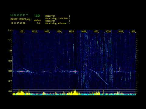
As the 60 and more satellites from Starlink 2 pass over the Graves radar signal they reflect a vertical track on the HROFFT radar image from the 143.05Mhz signal. In the first images the satellites are all still very close together, in current passes they have spread already and the display looks almost like rain in the sky on the 1 second radar plot from HROFFT.
Signal received with SDR RTL (SDRuno RSP1A) and 3 element Yagi at 45 degrees towards south