Category: Digital Signals

Transmitting DATV with a just a Raspberry Pi

All the way back in April 2014 we first posted about how the Raspberry Pi was able to transmit FM by cleverly modulating one of it’s GPIO pins. Later in October 2015 F5OEO expanded this idea and created software that allowed the Raspberry Pi to transmit not only FM, but also AM, SSB, SSTV and FSQ. Soon after some filter shields such as the QRPi were released to try and cut down on the spurious emissions caused by transmitting using this method.

Now F5OEO has once again taken this method a step forward and has created software capable of allowing the Raspberry Pi to transmit Digital Amateur TV (DATV). The software is called Rpidatv, and can be downloaded from https://github.com/F5OEO/rpidatv. It can be run from the command line, or via a touch graphical interface if you have a touchscreen LCD screen. DATV is a DVB-S broadcast and can be decoded with an RTL-SDR by using the leandvb software which is bundled together with the Rapidatv software. Previously we’d posted about how the International Space Station intends to one day transmit DATV and that it can be decoded with an RTL-SDR.

F5OEO writes that the software is capable of generating a symbol rate from 64k symbols to 1M symbols, which is enough to transmit one video with good H264 encoded quality. He also writes that using a low symbol rate may be useful for long distance transmissions as the signal will take up a smaller bandwidth. For example a 250K symbol transmission would only need 300kHz of bandwidth. He writes that this type of transmission could easily be used in the ISM band to replace WiFi video for FPV, but that at the moment video latency is about 1 – 2 seconds and is still being improved.

Once again we remind you that if you intend to transmit using these methods where a GPIO pin is modulated, then you MUST use a bandpass filter at the frequency you are transmitting at, and that you must be licensed to transmit on those frequencies.

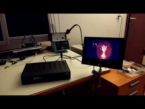
A DATV transmission received from a Raspberry Pi transmitter.

A new TETRA voice and multiframe SDS decoder

Recently Marek Sebera of ITDS Consulting wrote in to let us know about two new TETRA decoders that they have released. TETRA is a trunked radio communications system that stands for “Terrestrial Trunked Radio”. It is used heavily in many parts of the world, except for the USA.

The first piece of software released is called TETRA Listener and is from the Brmlab hackerspace in Prague. They write that Tetra-Listener is a new program (based on osmo-tetra) that can decode unencrypted voice and data traffic. They also write that it is very easy to set up and install since it uses Vagrant, which is a system that can be used to automatically set up a VMWare or VirtualBox Virtual Machine that has everything set up and ready to go. The instructions for using the software can then be found in the readme of the main tetra-listener page on GitHub.

The second software they have written is what they believe is the world’s first open source TETRA Multiframe SDS decoder. SDS stands for short data service and is the TETRA equivalent to SMS text messages used on a GSM network. They write that their solution can assemble long multiframe SDS messages.

Previously we showed how unencrypted TETRA messages could be listened to using telive in our tutorial. It is good to see alternative solutions now coming out, and in the future we hope to test this new software out.

TETRA SDS Example
TETRA SDS Example

Recent Updates to the JAERO L-Band and C-Band AERO Decoder

JAERO is a program by Jonti that was released late last year which allows us to use a SDR such as an RTL-SDR to receive L-band and C-Band AERO messages. AERO is essentially the satellite based version of ACARS, and the L-band signals contains short ground to air messages with things like weather reports and flight plans intended to be transmitted to aircraft. The C-band signals are the air to ground portion of AERO and more difficult to receive as they require an LNB and large dish. However they are much more interesting as they contain flight position data, like ADS-B.

Over March JAERO has had some minor updates. It is now possible to display planes on a map by using it’s SBS1 protocol output and outputting the data to Virtual Radar Server. The second more recent update now allows JAERO to simultaneously monitor up to two C-band AERO channels. To do this you will need to use the AUX VFO plugin for SDR#.

If you enjoy JAERO, please remember consider donating to Jonti.

Plotting flights positions out of regular ADS-B range which were demodulated from C-Band AERO signals by JAERO.
Plotting flight positions that are out of regular ADS-B range. Demodulated from C-Band AERO signals with JAERO.
Monitoring two C-Band channels in SDR# with the AUX VFO plugin.

Comparing ADS-B Reception with the RTL-SDR, Airspy and Beast Receivers

Over on satsignal.eu the author has set up a page showing live statistics of his ADS-B reception for the RTL-SDR and Airspy software defined radios, and also for the Beast ADS-B receiver. The Airspy is a $199 software defined radio that many consider as a next stage up from the RTL-SDR, and the Beast is a ~$270 USD dedicated ADS-B receiver.

Unsurprisingly the results clearly show that the Airspy receives ADS-B signals significantly better than the RTL-SDR. However, what comes as a surprise is that it is actually appears to be outperforming the dedicated Beast receiver. In the tests with the outside vertical antenna, the Airspy running on a Raspberry Pi appears to receive a significant higher number of messages and also sees planes out to a further range.

Not too long ago the Airspy team released their ADS-B software for the Raspberry Pi 2. They write that this software uses the full 10 MHz bandwidth and can even decode messages that are overlapping one another. We’ve also been told by the Airspy team that the Airspy is already in professional use as an ADS-B receiver amongst several small airports.

In the future we hope to compare the Airspy against the RTL-SDR on ADS-B reception ourselves, and also compare it against the 8 MHz bandwidth SDRplay whose development team have also recently released a new ADS-B decoder, as well as the recently released FlightAware ADS-B Prostick RTL-SDR.

Beast and Airspy comparison on ADS-B Reception.

A GNU Radio Based ISDB-T and RTL-SDR Compatible 1Seg Decoder

In most parts of the world the DVB-T standard is used to air digital HDTV. In the USA the ATSC standard is used, and in China DTMB is used instead. In other countries such as Brazil, Peru, Argentina, Chile, Honduras, Venezuela, Ecuador, Costa Rica, Paraguay, Philippines, Bolivia, Nicaragua and Uruguay a third standard called “ISDB-T International” is used which is based on the Japanese ISDB-T standard. 

Digital broadcast standards used in each country.

Recently a team from Uruguay has been working on creating a ISDB-T receiver in GNU Radio. With this decoder ISDB-T signals can be received with a wide bandwidth SDR (needs to be 6MHz or larger) and then decoded into a video file. Because ISDB-T is so similar to DVB-T they have based much of their code on gr-dvbt which is a GNU Radio based DVB-T decoder.

In addition to the ISDB-T decoder, they have also implemented a 1-seg decoder. 1-seg is a mobile HDTV service that exists in Japan, Argentina, Brazil, Chile, Uruguay and Peru. It runs on the ISDB-T system, and is called “1-seg” because it’s data occupies 1-segment of the 13-segment based ISDB-T bandwidth. It is used in small mobile TV receivers, many of which are now built directly into mobile phones sold in countries that use ISDB-T. Due to it’s much lower bandwidth requirement the 1-seg decoder can be used with an RTL-SDR dongle, and has already been tested to work.

A typical 1-seg capable Japanese mobile phone receiving digital mobile TV.
A typical 1-seg capable Japanese mobile phone receiving digital mobile TV. With the GNU Radio 1-seg decoder these transmissions can be received with an RTL-SDR.

Inspectrum: A New Tool for Analysing Captured Signals

Inspectrum is a Linux and OSX based tool that can be used for analysing captured signals. It is compatible with the IQ files generated from SDRs, such as the RTL-SDR or HackRF.

Over on YouTube user Mike has uploaded a video that demo’s the latest version of Inspectrum. He shows how the tool can be used to quickly browse the waveforms in a captured signal and how it can be used to determine various digital binary signal properties through an overlay that can be dragged to match the bit frequency of the captured signal.

This program looks like it is shaping up to be a very useful tool for those interested in reverse engineering digital signals. The Inspectrum code and installation procedure can be found at https://github.com/miek/inspectrum.

inspectrum tuner demo

Finding GPS Signals from within the Noise Floor with an RTL-SDR

If you were to try to simply spot a GPS signal at 1.575 GHz in the spectrum on a waterfall in a program like SDR# you would probably fail to see anything. This is because GPS signals are very weak, and operate below the thermal noise floor. Only through clever processing algorithms can the actual signal be recovered.

Previously GPS and SDR enthusiast “e.p.” showed us on his blog how to use an RTL-SDR and the GNSS-SDRLIB and RTKLIB software to receive GPS and get a position lock.

Now more recently e.p. has uploaded a post that explains a bit about how GPS signals are actually detected from below the noise floor. In his post he uses GPS data collected by his RTL-SDR dongle, and a fairly simple GNU Radio program consisting of a Fast AutoCorrelation Sink block.

With real data passed through the fast autocorrelation block he is able to observe GPS signal peaks that occur every millisecond. E.p. explains the reason for this:

Why every millisecond? The coarse/acquisition code for GPS (C/A) has a period of 1023 chips which are transmitted at a rate of 1.023 MBit/s. This results in period of 1 millisecond. BAM!

In a later post e.p. has also uploaded some sample GPS data collected with his RTL-SDR so anyone can play around with GPS decoding.

Autocorrelation of a GPS signal resulting in peaks every millisecond.

Using Multiple RTL-SDR’s to Capture a Trunking System

An RTL-SDR dongle has a maximum usable bandwidth of about 2.4 MHz which most often isn’t enough to capture an entire trunking system that may be spread out over a larger bandwidth. In order to get around this limitation Luke Brendt has been using three RTL-SDR dongles together to capture a trunking system in his area which is spread over 6 MHz of bandwidth.

Luke uses his own Trunk Recorder software and writes that he has modified it to support multiple SDR’s. His software has the following description:

Trunk Recorder is able to record the calls on a trunked radio system. It uses 1 or more Software Defined Radios (SDRs) to do. The SDRs capture large swatches of RF and then use software to process what was recieved. GNURadio is used to do this processing and provides lots of convienent RF blocks that can be pieced together to do complex RF processing. Right now it can only record one Trunked System at a time.

  • Trunk Recorder currently supports the following:
  • P25 & SmartNet Trunking Systems
  • SDRs that use the OsmoSDR source ( HackRF, RTL – TV Dongles, BladeRF, and more)
  • Ettus USRP
  • P25 Phase 1 & Analog voice

Luke also mentions that using three RTL-SDRs like this seems to be more efficient on the CPU than using a single SDR that has 8 MHz of bandwidth due to the amount of down sampling that needs to be done on larger bandwidth SDRs. 

When I was using a single SDR, each Recorder had to take in the full 8MHz and pull out the small 12.5KHz that was interesting. The end results is that I could only record about 3 channels at once before the CPU got overloaded. Since that control channel was going at the same time, that was the equivalent of about 32MHz of bandwidth to process.

With the RTL-SDR, each Recorder only has to look at 2MHz, which puts a lot lighter load on the CPU. Roughly speaking, having 3 Recorders active, plus the control channel would mean that only a total of 8MHz was being processed. As you can see, this means that it scales much more efficiently.

Using three RTL-SDR's to monitor a 6 MHz trunking system.
Using three RTL-SDR’s to monitor a 6 MHz trunking system.