KerberosSDR: Tracking a Weather Balloon Radiosonde with Radio Direction Finding

The KerberosSDR is our 4-channel phase coherent capable RTL-SDR unit that we previously successfully crowdfunded back in 2018.  With a 4-channel phase coherent RTL-SDR interesting applications like radio direction finding, passive radar and beam forming become possible. It can also be used as 4 separate RTL-SDRs for multichannel monitoring.

KerberosSDR can be purchased from our partner store at https://othernet.is/products/kerberossdr-4x-coherent-rtl-sdr.

In one of our latest tests we've been able to track a weather balloon radiosonde via the direction finding ability of KerberosSDR. These balloons are launched twice daily by meteorological agencies around the world, and the radiosonde carried by the balloon transmits an RS-41 signal continuously throughout it's flight sending back telemetry such as weather information and GPS coordinates. The KerberosSDR tracks the bearing towards the balloon using only the raw signal - it does not decode. Having the actual GPS location from the RS41 data allows us to compare and confirm that the KerberosSDR is indeed tracking the bearing of the balloon.

In this test we used the excellent 4-element dipole array made by Arrow Antennas. In particular we used the 406 MHz element version as the RS-41 signal is broadcast at 403 MHz. The antenna array is mounted on the roof, the KerberosSDR is in the attic connected to a Raspberry Pi 4. Our KerberosSDR Android app is used to plot the bearings. A separate RTL-SDR running on the video recording PC is connected to it's own antenna and is used to receive and decode the RS41 signal. The free software RS41 Tracker is used to decode and map the balloon for location confirmation. 

We are currently using the latest beta code in development (unreleased at the time of this post - it will be released within 1 to 2 months) which handles non-continuous intermittent signals better.

Arrow Antennas 4-Element Dipole Array Mounted on Roof

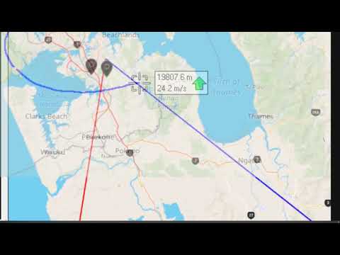
The short video below shows a timelapse of the RS41 decoder tracking a balloon which circled the south of our KerberosSDR. The red line indicates the zero degree direction of the antenna array, while the blue line indicates the estimated direction of the balloon determined via the MUSIC radio direction finding technique.

The GPS balloon map from RS41 tracker is overlayed on top of the KerberosSDR Android app map for clarity via video editing. We can see that it mostly tracks the balloon to within a few degrees. When the blue bearing line diverges this is due to the balloon's line of sight path to the antennas being obscured by terrain, buildings or trees. When this is the case a multipath signal reflecting off surrounding hills tends to become dominant.

In the second short video below the weather balloon tracked northwards. Towards the north, north west and north east we have antenna obstructions in the form of rising terrain, houses and hills, so the overall accuracy is poorer. However, it still tracks within a few degrees most of the time.

Finally the YouTube video below shows the same as the above, but in the second half includes the full screen including the KerberosSDR DoA graphs and SDR# waterfall showing signal strength.

KerberosSDR Tracking a Weather Balloon Radiosonde with Radio Direction Finding

In the future we hope to test with two or more KerberosSDR units producing multiple bearing lines on RDFMapper, hopefully resulting in cross points that can be used to estimate the actual location of the balloon.

A Handheld SciFi Scanner Box with RTL-SDR and Thermal Camera

Over on his YouTube channel "saveitforparts" has been working on creating a handheld scanner/sensor box on a budget. This is a simple and fun build which is attempting to create something like a real life Star Trek scifi tricorder that you might imagine taking with you to analyze systems on another planet. The box embeds a Raspberry Pi, USB hub, battery pack, RTL-SDR and thermal camera inside. In the video he shows how everything fits into the box and gives a quick demo of the RTL-SDR and thermal camera in action. In the future he plans to add more sensors as well.

Handheld Scanning Device with Raspberry Pi - Part 2

BSides Talk: It’s 2020, so why am I still able to read your pager traffic?

At the BSides OK 2020 virtual conference Cameron Mac Millan recently presented a talk titled "It’s 2020, so why am I still able to read your pager traffic?". On this blog we have posted numerous times about privacy breaches stemming from insecure wireless pager traffic. Anyone with a radio or SDR can receive and decode pager messages, and this has been known and done since the 1980's. Cameron's talk explains how paging systems work, who are the modern users of pagers, how to capture and decode pager messages and how to best log and filter through messages. He goes on to describe a number of major pager security breaches that he's personally seen. The talk preview reads:

This talk explores why pagers remain a potential threat vector in many environments despite the technology being 40 years old. This is not a the-sky-is-falling presentation: everything from paging history to how simple it is to decode pager traffic (and the associated risks) is covered without FUD.

I enjoy poking things with sticks and turn over rocks to see what crawls out from under them. One of my interests is seeing how technologies believed to be obsolete can still pose a problem for security today, and do that from the perspective of a 20-year career in infosec. When not creating tomorrow’s problems with yesterday’s technology, I can usually be found wrenching on unusual cars.

It’s 2020, so why am I still able to read your pager traffic? - Cameron Mac Millan - BSidesOK 2020

Eavesdropping on LTE Calls with a USRP Software Defined Radio

Ars Technica recently ran a story about how University researchers have been able to eavesdrop on LTE mobile phone calls using a USRP B210 software defined radio which runs the Airscope software. The technique exploits a flaw in how some LTE carriers are implementing their keystream. A keystream is a stream of random data combined with the actual voice data, resulting in encrypted data.

It turns out that many LTE carriers reuse the same keystream when two calls are made within a single radio connection. An attacker can then record an encrypted conversation, then immediately call the victim after that conversation. The attacker can now access the encrypted keystream, and as the keystream is identical to the first conversation, the first conversation can now be decoded. 

The Ars Technica article, the original paper and a website created about the ReVoLTE technique and software go into detail about how the attack works. On the website the team explain the attack in simple terms:

The ReVoLTE attacks exploit the reuse of the same keystream for two subsequent calls within one radio connection. This weakness is caused by an implementation flaw of the base station (eNodeB). In order to determine how widespread the security gap was, we tested a number of randomly selected radio cells mainly across Germany but also other countries. The security gap affected 12 out of 15 base stations.

The ReVoLTE attack aims to eavesdrop the call between Alice and Bob. We will name this call the target or first call. To perform the attack, the attacker sniffs the encrypted radio traffic of Alice within the cell of a vulnerable base station. Shortly after the first call ends, the attacker calls Alice and engages her in a conversation. We name this second call, or keystream call. For this call, the attacker sniffs the encrypted radio traffic of Alice and records the unencrypted sound (known plaintext).

For decrypting the target call, the attacker must now compute the following: First, the attacker xors the known plaintext (recorded at the attacker's phone) with the ciphertext of the keystream call. Thus, the attacker computes the keystream of the keystream call. Due to the vulnerable base station, this keystream is the same as for the target (first) call. In a second step, the attacker decrypts the first call by xoring the keystream with the first call's ciphertext. It is important to note that the attacker has to engage the victim in a longer conversation. The longer he/she talked to the victim, the more content of the previous communication he/she can decrypt. For example, if the attacker and victim spoke for five minutes, the attacker could later decode five minutes of the previous conversation.

The ReVoLTE Attack
Demonstration of the ReVoLTE attack in a commerical LTE network.

DragonOS: Installing Crocodile Hunter For Detecting Fake 4G Cell Sites

A few days ago we posted about two SDR related DEFCON talks which were recently released. One of the talks was about detecting fake 4G base stations with a bladeRF SDR and a tool they created called "Crocodile Hunter". It is currently compatible with the bladeRF x40 and USRP B200. The talk summary is posted below as it nicely summarizes what fake 4G base stations are and what Crocodile Hunter can do.

4G based IMSI catchers such as the Hailstorm are becoming more popular with governments and law enforcement around the world, as well as spies, and even criminals. Until now IMSI catcher detection has focused on 2G IMSI catchers such as the Stingray which are quickly falling out of favor.

In this talk we will tell you how 4G IMSI Catchers might work to the best of our knowledge, and what they can and can't do. We demonstrate a brand new software project to detect fake 4G base stations, with open source software and relatively cheap hardware. And finally we will present a comprehensive plan to dramatically limit the capabilities of IMSI catchers (with the long term goal of making them useless once and for all).

The Crocodile Hunter software is apparently a little difficult to install and get running, so Aaron who runs DragonOS YouTube tutorial channel has uploaded a video documenting how to install and configure the software. The tutorial assumes that you are the running the latest DragonOS image which already includes a lot of the prerequisite software, and in his example he uses a USRP B205mini-i SDR.

DragonOS DEF CON 28 Crocodile Hunter Setup (DragonOS LTS PublicR4, srsLTE, USRP B205mini-i)

TechMinds: OpenWebRX Feature Overview And Raspberry Pi Setup

Over on YouTube TechMinds has posted his latest video which shows an overview of the features available in OpenWebRX, and also how to set it up on a Raspberry Pi. OpenWebRX is software which allows you to access your SDR remotely via the internet or local network through a web browser. All major SDRs are supported including RTL-SDRs. The software includes a waterfall display, all the standard demodulators, as well as several digital decoders for DMR, YSF, NXDN, D-Star, POCSAG, APRS, FT8, FT4, WSPR, JT65 and JT9.

In the video TechMinds first demonstrates OpenWebRX in action, showing reception of HF SSB amateur radio signals, decoding FT8 and plotting received grids on a map, decoding and plotting APRS on a map and decoding YSF/DSTAR/DMR digital voice. After this demonstration he goes on to show how to set up the OpenWebRX server on a Raspberry Pi via the installation image.

OpenWebRX Feature Overview And Raspberry Pi Setup

Sanchez: Create False Colour Images from GOES/Himawari/GK-2A Infrared

With an RTL-SDR, an appropriate satellite antenna and LNA it is possible to receive visible light images from geostationary satellites such as GOES/Himawari and GK-2A. However, in a 24 hour cycle there will only be one or two images that show the Earth fully illuminated by the sun. The rest of the day parts or all of the Earth will be dark with not even clouds visible. To get around this the satellites also use an Infrared (IR) camera which can see clouds at all times. However, these images are greyscale and not very visually appealing.

To fix this aesthetic issue there is now a recently released multiplatform tool called "Sanchez" which will combine a high resolution underlay image with the greyscale IR image in order to create a more beautiful image. The software is command line based and can run on a batch of collected images.

False colour satellite images made by Sanchez

Testing the Electrosense Up/Downconverter Expansion Board For 0 – 6 GHz

The Electrosense network is an open source project aiming to deploy radio spectrum sensors worldwide. The idea is to help analyze and understand radio spectrum usage across the globe. Each sensor consists of an RTL-SDR, Raspberry Pi and an optional downconverter to receive the higher bands. If you're interested we wrote an overview of the project in a previous post

Recently we received a sample of their Up/Downconverter expansion board which is used to expand the frequency range of the RTL-SDR to 0 MHz to 6 GHz. The converter board is entirely open source with the design files available on GitHub. The team note that they are also working on a V2 version which will be cheaper and smaller. The schematic and Firmware for the V2 is also available right now, but it is still under early testing and may change.

The board is not for sale, however you can apply to be considered for a free unit if you want to host your own Electrosense node and meet their criteria. If you do not you can still produce the board yourself. The team mention that the design is easily hand soldered, but there are a few difficult LGA components like the PLL, crystals and mixer which require a heat gun to solder. A the same time they also note that it is possible to get PCB manufacture and SMT assembly done for you for dirt cheap by PCB prototype companies like JLC PCB. 

The Expansion Up/Downconverter Board

The converter board has 4-input SMA ports (only 3 are used) and one output port which connects to the RTL-SDR. The first input port is for the HF antenna input. This input connects to the circuit which converts 0 - 30 MHz into a higher frequency which can be received by the RTL-SDR. The second port is simply a pass through for the standard 24 MHz - 1.766 GHz range of a normal SDR. The third port is unused, and the fourth port connects the antenna to the downconverter circuit which allows us to receive from 1.766 GHz to 6 GHz.

The Electrosense Converter Board

Continue reading