WSPR is an amateur radio digital HF mode designed to be decodable even if the signal is transmitted with very low power and is very weak. It can be used to help determine HF radio propagation conditions as WSPR reception reports are typically automatically uploaded to wsprnet. Direct sampling mode on the RTL-SDR V3 allows you to receive HF signals without the need for an upconverter. For best results it is recommended to use a simple bandpass filter for the band of interest.
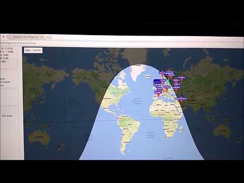
Zoltan's tutorial comes with a companion YouTube video where he demonstrates his set up. He uses a random wire antenna on his roof directly connected to an RTL-SDR V3, which is connected to a Raspberry Pi 3. The Pi 3 communicates to his home network via an Ethernet cable.
Making a standalone WSPR receiver with RPi and RTL-SDR V3 using rtlsdr-wsprd
The PlutoSDR is an Analog Devices $99 - $149 RX/TX capable SDR with 20 MHz of bandwidth and a 325 MHz to 3.8 GHz frequency range that is software hackable to 56 Mhz of bandwidth and a 70 MHz to 6000 MHz frequency. It has an on board Xilinx Zynq Z-7010 FPGA, which has a built in dual core ARM Cortex-A9 processor as well. This processor is capable of running Linux and Linux SDR software on the PlutoSDR itself. PlutoSDR's can be purchased directly from Analog Devices, or via Arrow, DigiKey or Mouser.
Recently "Lama Bleu" has been working on a custom firmware image for the PlutoSDR. Installing custom firmware allows you to load up a pre-configured Linux system which already has a bunch of useful software installed. He writes that his version is not designed to have a nice GUI, but rather focuses on scripting and data acquisition software. A list of software pre-installed to the image is shown below:
gnuplot + libpng ---> signal.sh script to acquire and plot directly on the pluto using rx_power.
Busybox utilities : netcat, at, timeout, ntpd and more (at and timeout to perform scheduled tasks or end a task).
morfeus_tool !
To access these tools you simply connect to the PlutoSDR via a network connection and SSH. With some of the tools installed it is possible to do things on board the PlutoSDR like recording signals, demodulating signals, transmitting CW, stream demodulated audio over a network, plot the spectrum on the terminal, create an online SDR with OpenWebRX, do a long spectrum scan and transmit DATV.
An alternative custom firmware is PlutoWeb which we posted about in the past. This image is designed for creating a web interface GUI, and for running streaming software such as OpenWebRX.
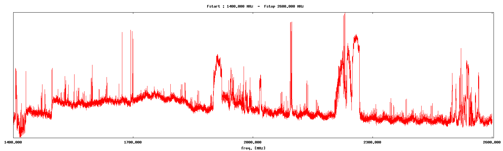
A spectrum scan completed on board a PlutoSDR with rx_tools, running Lama Bleu's custom firmware.GNU Plot running on the PlutoSDR with Lama Bleu's custom firmware.
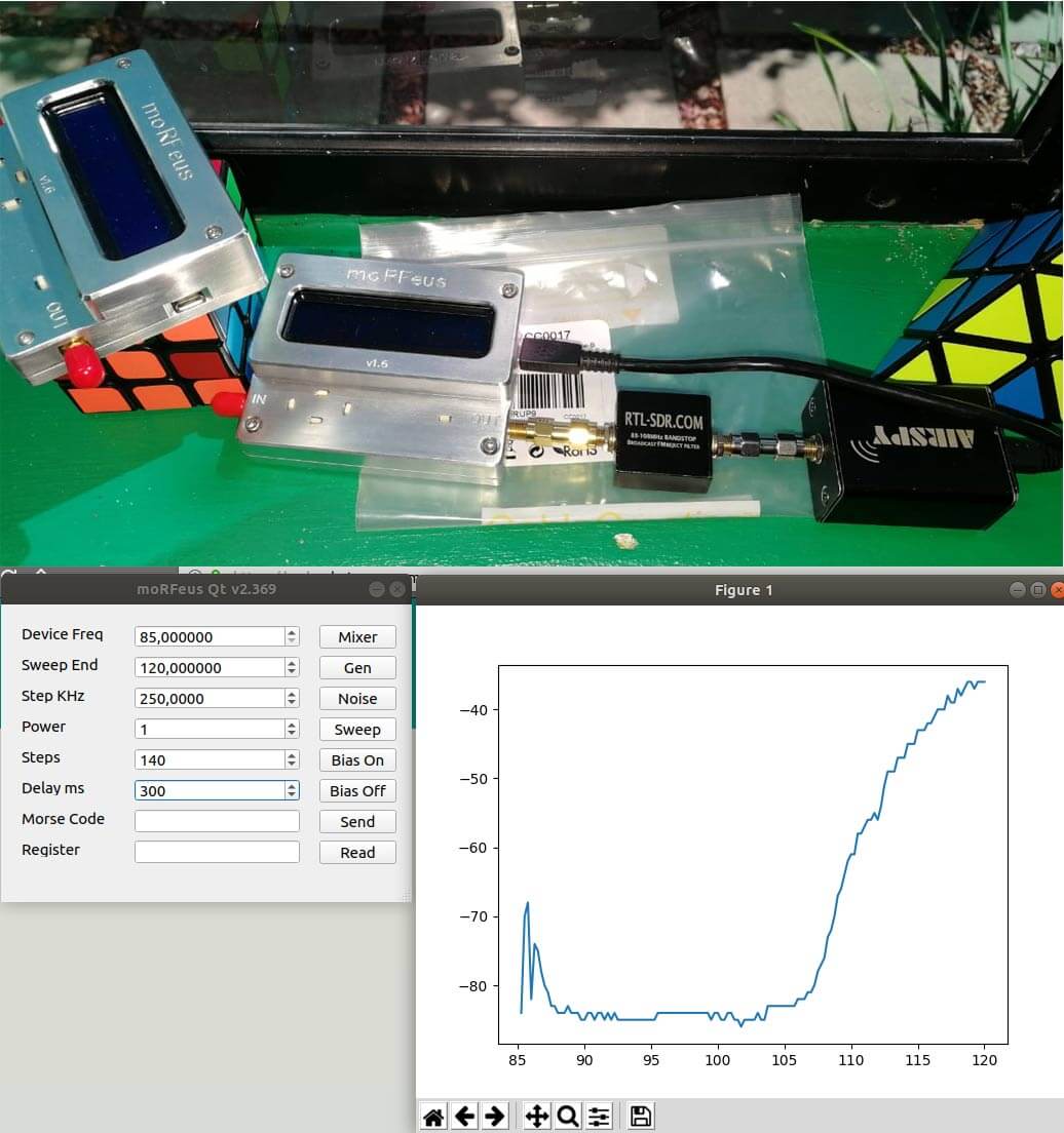
Outernet's moRFeus is a signal generator and frequency mixer that can be controlled either by it's built in LCD screen, or via software on a Windows or Linux PC. It can generate a clean low phase noise tone anywhere between 85 to 5400 MHz. Because it can be computer controlled it is possible to use moRFeus as a tracking generator for characterizing filters and measuring antenna SWR. A tracking generator is just a signal generator that can be set to output at the same frequency that the measurement receiver is tuned to.
In the past we've posted about some software developed by Ohan Smit, which allows a moRFeus to be controlled on a Windows/Linux PC via a nice GUI. Recently he's updated the software and it can now draw power (dbFS) graphs for characterizing filters when combined with an Airspy and TCP comms to GQRX. Ohan writes:
So when you press sweep, it detects if there is any TCP servers on port 7356 and if so tunes the radio and gets a power measurement and after the sweep is done, morfeusqt renders a graph on the fly.
It now also supports multiple devices, no configurations required. It just opens another window for the second device.
These features thus far work on both Windows 10 and Ubuntu 18.04.1, these are my two testing environments with GQRX and the Airspy.
Ohan also notes that he's working on several new features such as the ability to plot VSWR, remote control of the moRFeus via TCP, support for multiple SDR TCP protocols such as rtl_tcp, soapytcp etc, threading and progress bars, as well as possibly support for cheap Osmo-FL2K devices as a tracking generator.
You can follow his developments live on the Outernet forums.
moRFeus used as a tracking generator with an Airspy with the morfeusQT software
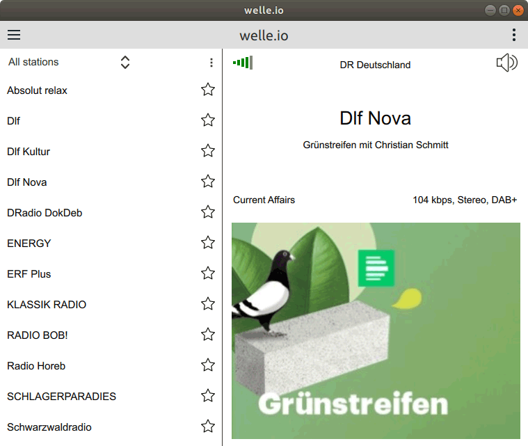
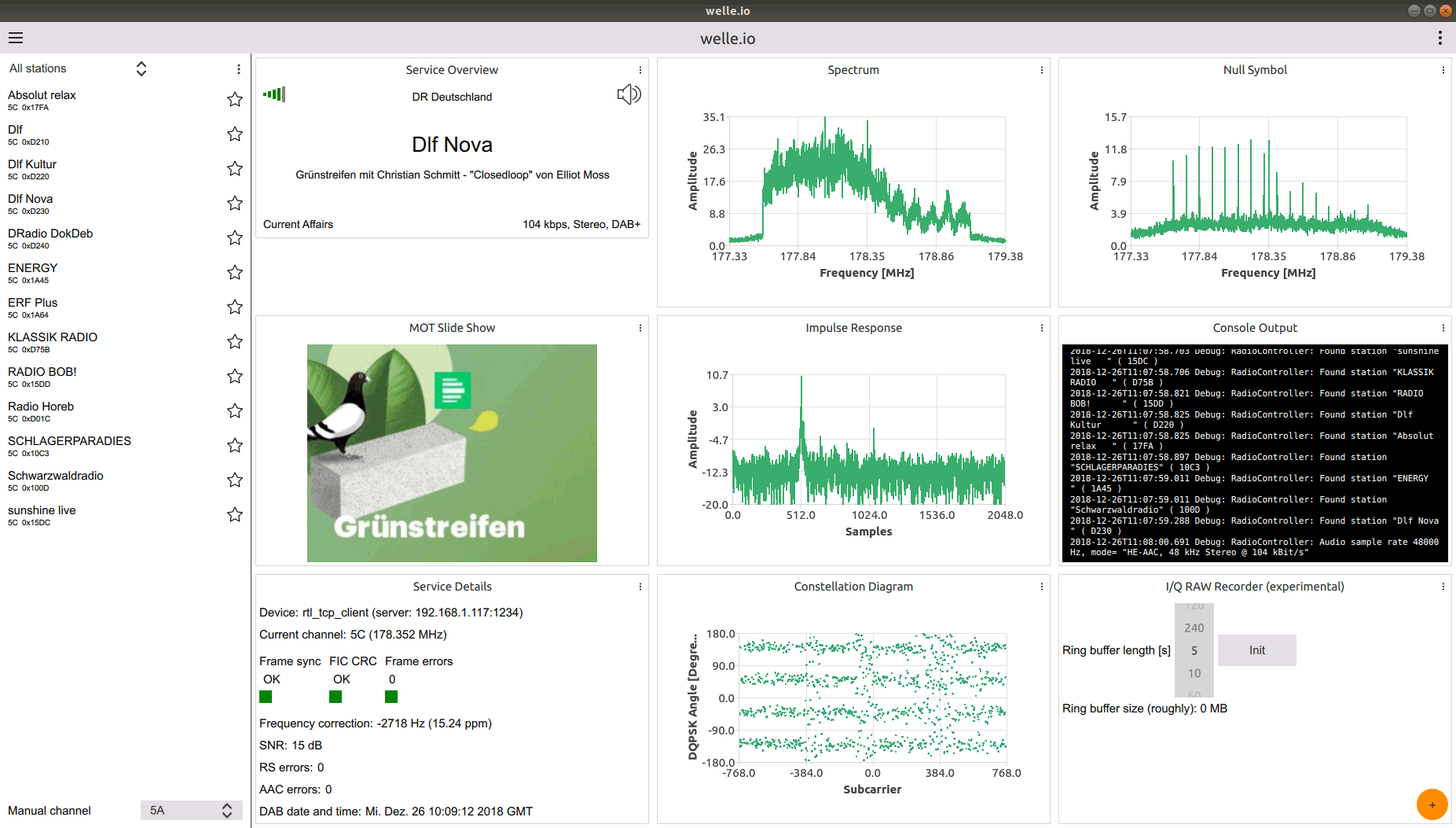
Welle.io is a Windows/Linux/MacOS/Android/Raspberry Pi compatible DAB and DAB+ broadcast radio decoder which supports RTL-SDR dongles, as well as the Airspy and any dongle supported by SoapySDR. It is a touch screen friendly software which is excellent for use on tablets, phones and perhaps on vehicle radio touch screens.
Thank you to Albrecht Lohofener, the author of welle.io for writing in and sharing his news about the release on welle.io version 2.
welle.io 2.0 Beta 1 released
I’m happy to announce the version welle.io 2.0 Beta 1. Since the first rtl-sdr.com post roughly two years ago (Mar 2017) welle.io became the leading open source DAB/DAB+ SDR. Many people are using welle.io in their daily life and gave a lot of feedback.
With all this feedback we started developing the version 2.0. Apparently, the biggest change is the complete redesign of the user interface (GUI). It changed from a dark design to a bright design and handles easily different screen resolutions and orientations.
Many users asked for a favorite list, automatic playing of last station and a mute button. Now these features are ready to test with the 2.0 Beta 1!
Another new feature is the settings menu where users can set the hardware receiver with all the necessary settings. This is more user friendly than the command line parameters.
For people with a deep technical interest we improved the expert mode a lot. In addition to the spectrum users can also view the impulse response, null symbol and constellation diagram, even at the same time! An experimental I/Q RAW file recorder as well as a debug output window is available for systems without a text console.
In the back-end we improved the multi-path behavior and started a source code refactoring to allow the code to be easily maintained. Great thanks to the people from the Opendigitalradio association (http://www.opendigitalradio.org/) which are actively contributing to this project.
Now it is possible to build a complete DAB/DAB+ system (transmitter and receiver) with open source!
As a result from this collaboration welle-cli is available. The main use case is to monitor DAB/DAB+ transmitters networks over the internet. Thus it has a HTTP API and includes a basic Web page which shows the features.
Everyone is invited to test the new version and to report issues. For reports we recommend to open an issue at the welle.io Github page (https://github.com/AlbrechtL/welle.io/issues).
We are also looking for people who would like to contribute to welle.io (translations, web page, documentation and development).
Over on YouTube SignalsEverywhere (aka Corrosive) has uploaded a tutorial video showing how to use TempestSDR with an Airspy SDR. Back in November 2017 we posted about how we were able to get TempestSDR to run with an RTL-SDR, Airspy and SDRplay, and showed some results. Since then several people have managed to repeat our results, but many have also had trouble understanding how to make TempestSDR work and what all the settings are for.
TempestSDR is an open source tool that allows you to use any SDR that has a supporting ExtIO (such as RTL-SDR, Airspy, SDRplay, HackRF) to receive the unintentional signal radiation from a screen, and turn that signal back into a live image. This can let you view what is on a screen without any physical connections.
Corrosive's tutorial video shows us how to tune the signal in the TempestSDR software in order to receive a clear image as well as showing the software in action.
How to Spy on Computer Monitors | TempestSDR Tutorial (with an Airspy)
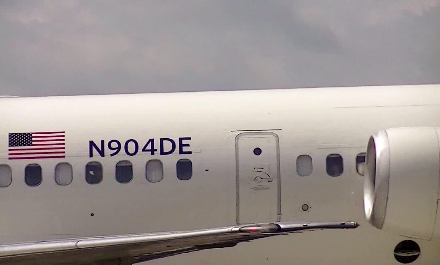
For ADS-B decoding, dump1090 is an RTL-SDR compatible program that is commonly used. In order to provide information about the aircraft being detected (e.g. icao24 hex address, registration/tail number and sometimes the type of aircraft like A380), dump1090 uses an offline database. Unfortunately this database has not been maintained in a very long time, so it is now out of date, and so cannot display information about many aircraft.
Contained within the data is the icao24 hex address and registration/tail number. By collecting this VDL2 data over a number of days, a new database can be generated which can then be imported into the dump1090 database. It however, doesn't seem to acquire aircraft type data.
An aircraft registration/tail number displayed on the fuselage. Image source: Wikipedia
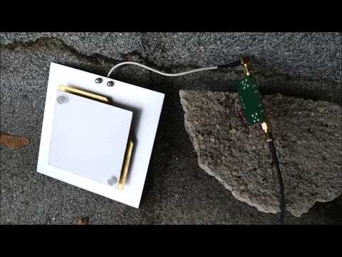
Thanks to Zoltan (aka Veryokay on YouTube) for submitting information about his Inmarsat STD-C EGC live stream setup. His setup allows him to access the Inmarsat STD-C signal from anywhere in the world over the internet, thanks to the use of an OpenWebRX server. Inmarsat STD-C is a geostationary satellite service that provides information for search and rescue, as well as news, weather and incident reports for mariners. We have a tutorial from a few years ago which shows some example messages. OpenWebRX is an efficient SDR streaming server platform that allows you to access RTL-SDR's and other SDRs from anywhere in the world via an internet connection.
In his setup Zoltan uses a Raspberry Pi 3, RTL-SDR Blog V3, L-band LNA and L-band antenna for receiving and processing the signal. Power is provided via a Power over Ethernet (PoE) adapter, and the whole thing is placed outside, in a weatherproof plastic lunchbox.
The video shows the hardware, and then goes on to describe the software setup, along with a demonstration of the OpenWebRX stream. More information as well as the link to his publicly accessible OpenWebRX Inamrsat STD-C stream can be found on his blog post.
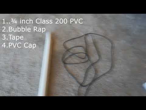
Thank you to YouTube user "ModernHam" for submitting his video that shows one way to weatherproof our 'RTL-SDR Blog Multipurpose Dipole Antenna'. This is the antenna we include as part of our RTL-SDR kit, and it is an excellent beginners antenna. Dipole antennas typically receive better than mag-whips, are easier to mount on windows, and can receive 137 MHz weather satellites too.
However, due to their portable telescopic collapsible design, our antennas are not designed for permanent outdoor use as dirt and grime can gum up the collapsing mechanism. In his video ModernHam decided to waterproof the dipole for permanent outdoor mounting. To do this he modified the plastic base by cutting it down, and then places the dipole inside a PVC pipe with some bubblewrap used to hold it in place. This keeps the elements out, and looks pretty good mounted up high too.