Airspy and Spyverter using a GPSDO

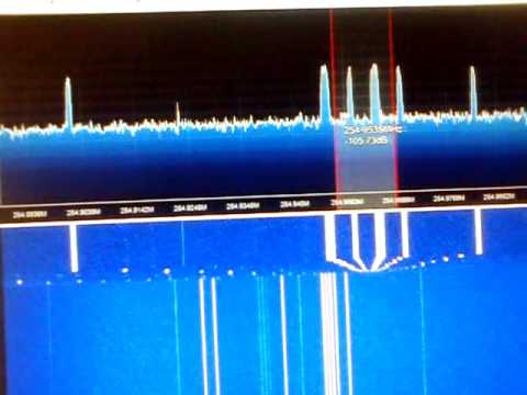
Recently Tim Havens (NW0W) wrote in to use to let us know about his work in connecting the Airspy and Spyverter to a very accurate GPS disciplined oscillator (GPSDO). Usually the drift on the Airspy and Spyverter is completely negligible, however Tim uses them together with his Yaesu FTDX-5000 for monitoring CW signals. He wanted to be able to click on a CW signal and have his FTDX-5000 tune to the signal perfectly every time, so even very small oscillator drift offsets could affect his tuning.

To get a high accuracy clock signal from a device such as a GPSDO can be used for both the Airspy and Spyverter. Tim was able to find a very nice GPSDO from Leo Bodnar that comes with two clock separate outputs that can be configured to output any frequency between 450 Hz and 800 MHz. 

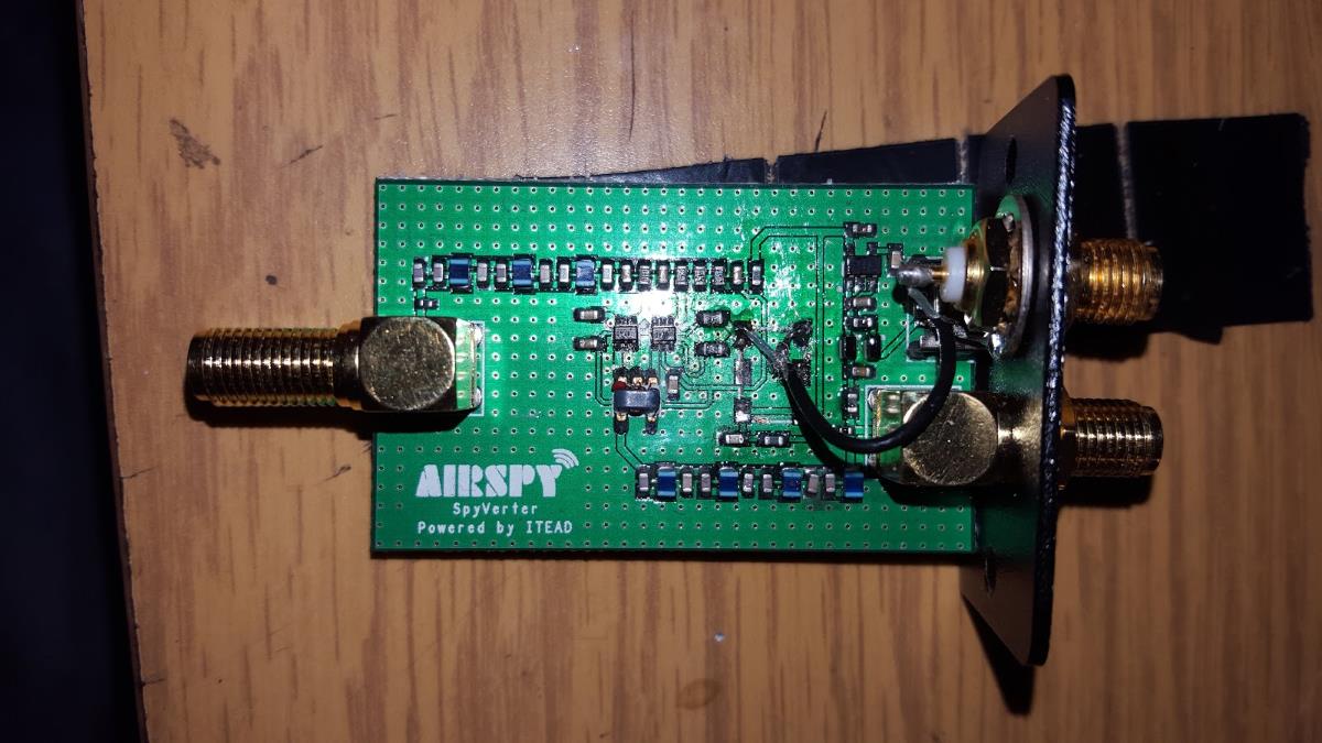
The Airspy already contains an external clock input for 10 MHz, however the present version of the Spyverter contains no such external input. To get around this Tim carefully removed the oscillator on the Spyverter and then added a second SMA connector to connect to the GPSDO.

His final setup consists of the Leo Bodnar GPSDO outputting a 10 MHz and 120 MHz GPS disciplined clock signal that feeds the Airspy and Spyverter respectively. With this Tim found that he needed no initial offset and zero drift was noticed over two days of testing.

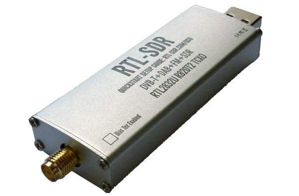
Finally Tim also writes that this Leo Bodnar GPSDO could just as easily be used to create a 28.8 MHz clock signal for an RTL-SDR, or any other SDR or upconverter that needs it. 

Modded Spyverter with external clock input.

Receiving AERO-H on L-Band with an RTL-SDR

Over on YouTube Adam Alicajic (9A4QV – creator of the LNA4ALL and upcoming MIX4ALL) has uploaded a video showing his reception of AERO-H signals from an Inmarsat satellite. A few days ago we posted about how the JAERO decoder had recently been updated to be able to decode these AERO-H signals. These signals contain various messages meant for airplanes, but also sometimes contain news messages.

In the video Adam uses a satellite dish antenna together with his MIX4ALL, an RTL-SDR dongle and the JAERO software. With decent reception he is able to easily decode the AERO-H messages.

Receiving AERO-H on L-band (Inmarsat AOR-W)

Demonstrating Radio Frequency Interference with an Airspy

Over on YouTube user Ejo Schrama has uploaded a short video showing a demonstration of radio frequency interference (RFI) from various Arduino based devices he’s built. The interference comes from the local oscillators within the devices which are common to many electronic devices. He writes in the video description:

RFI simply means that there is a part in the radio spectrum that we wouldn’t like to see, it is usually unintentionally caused by devices around us (computers, televisions, radios, clocks, watches, etc etc) that carry local oscillators which are low power transmitters. Sometimes it is caused by illegal transmissions, so a deliberate action.

The oscillators of devices around us oftentimes feed digital circuits, sine wave become block wave, as a result higher order harmonics of the block wave pollute the spectrum. If your receiver is sensitive enough then you will pick up the RFI at some point.

In this video I’m two meter away from an antenna and I tuned the receiver to 48 MHz which is the 3rd harmonic of the 16 MHz oscillator used by all nearby Arduino experiments. Lets see what the spectrum does by turning on and off some arduino’s. The worst RFI generator was a 16 MHz atmel 328p multiplexing four 7-segment LEDs displaying the value of a IR temperature sensor. But also a nearby clock experiment clearly caused some RFI.

The receiver that I used was an airspy, and I’ve put the decimation factor high enough to get some resolution in the spectrum. The frequency offset between the different arduino’s is clearly visible. This is caused by the fact that cheap quartz oscillators are used, their accuracy is usually around 100 ppm, and this mostly determines a frequency bias.

Nowadays it is very difficult to clean up your local shortwave spectrum. For this reason reception conditions under 30 MHz and even 2 meter nowadays face the RFI problem. Only when we go to UHF frequencies like 430 MHz, better known as the the 70 cm amateur band, the RFI problem sort of disappears, apparently because higher harmonics have become insignificant.

I do not think that a lot of effort is put into keeping LW, HF but also VHF spectra clean, the worst violators are usually tracked down but only when many listeners start to complain.

Hacking the Z-Wave Protocol with a HackRF

Z-wave is a wireless protocol that is used often in applications like smart home and industrial automation. It essentially allows various wireless nodes to connect and talk to one another within your house, using 900 MHz wireless technology. Some common examples of Z-wave node products might be wireless controlled lights, door locks, thermostats and other security devices like motion detectors.

Recently at Shmoocon 2016 (a yearly hacking and security themed conference), presenters Joseph Hall and Ben Ramsey showed how they were able to use a HackRF software defined radio and some GNU Radio based software to not only sniff Z-wave packets, but to also control Z-wave devices. What’s also interesting is that they found that encryption on z-wave devices was rarely enabled, except for five out of nine door locks that they tested where it was enabled by default.

See the full story at Hackaday and have a look at their code on GitHub.

Joseph and Ben holding a HackRF and z-wave controlled light.
Presenters Joseph and Ben holding a HackRF and z-wave controlled light.

RTL-SDR.com SDR Dongle Giveaway!

We are giving away 20 of our new units with the metal case!

Competition has now ended! Thanks to all who entered! Winners to be announced by Monday.

The RTL-SDR and SDR community spans multiple disciplines and there are many wildly different projects being worked on by SDR enthusiasts as regular readers of our blog may already know. We want to thank all our readers with a competition and at the same time get everyone to share what projects you are all working on.

There are four chances to enter the contest and you may enter in all four competitions. On each method we will give away 5 RTL-SDR blog dongle + antenna units. Competition ends in one week on the 22nd of January at 23:59 hrs (midnight) PST time. Winners will be notified in the following 1-2 days and we will do a post about it too.

Competition Entry 1) Like us on Facebook and make a comment on the the contest post mentioning what SDR related projects you are currently working on, or plan to work on in the future.

Competition Entry 2) Follow us on Twitter and tweet at us @rtlsdrblog mentioning the SDR related projects you are currently working on, or plan to work on in the future.

Competition Entry 3) Make a comment on this very blog post mentioning what SDR related projects you are currently working on, or plan to work on in the future. (Please include a contact email address in the email field – it will only be visible to us and we won’t use it for anything else, promise!)

Competition Entry 4) Sign up to our email mailing list here or on the right hand navigation menu. (we send out a once weekly digest of the weeks posts).


We want to hear about any and all projects, no matter how simple you might think they are! At the end of the competition we will randomly select five winners from each competition entry method and contact them. Please remember to check your Facebook/Twitter/email accounts if your name comes up when the winners are announced.

Rules: Only one entry per person per method! E.g. you can enter once on Facebook, once on Twitter, once by commenting here, and once by signing up to our mailing list. No duplicate accounts are allowed. You must be legally be allowed to receive and own an RTL-SDR dongle to enter.

New RTL-SDR Dongles with Metal Case Available in our Store

Currently we at RTL-SDR.com are selling upgraded RTL-SDR dongles on our store. We’ve worked hard to reduce the most common issues that the cheapest generic dongles have, whilst trying to not significantly increase the retail price so that these devices stay ubiquitous. In each batch that we’ve produced so far we’ve tried to make some improvements over the last. Previously we’ve added a TCXO, SMA connector, and bias tee and now in the latest batch we’ve added a metal case and passive cooling.

The new units have been in stock at our Chinese warehouse for almost a month now, and they are now back in stock at Amazon USA as well (shipping soon). They are priced the same as before: $24.95 USD for the unit with antennas and $19.95 USD for the dongle only. If you order from the Chinese warehouse all units come with free registered air mail shipping (1-4 week delivery), and free shipping is available on Amazon for USA customers (<1 week delivery) if you are a Prime member or spend over $35.

To purchase please see our store page at www.rtl-sdr.com/store.

New features in this version:

  • Aluminium case. We’ve upgraded from a plastic case and now all units come with an aluminium case standard. The aluminium is 1mm thick and is treated with an anti-anodizing coating to improve conductivity. However, some natural anodization still occurs. The dimensions are similar to the plastic case at 69 mm x 27 mm x 13 mm.
The new RTL-SDR dongle design with aluminium case.
  • Ground tracks on the PCB. The PCB size has been increased slightly to accommodate side ground tracks. These ground tracks should make contact with the aluminium and provide ground conductivity to the case.
New RTL-SDR PCB with side ground tracks.
  • Passive cooling. As the case is now metal we can apply a thermal interface material between the PCB bottom and case wall. The interface material we’ve chosen is a 3mm thermal pad. This is a soft silicon pad with high thermal conductivity. This appears to provide adequate cooling to ensure the dongles run properly at above 1.5 GHz.
Thermal pad on the bottom of the PCB for improved heat dissipation.

The metal case and side ground tracks should reduce the amount of interference received by the dongle through sources other than the antenna. The passive cooling should also be enough to ensure that the dongles run properly at above 1.5 GHz, though we still would recommend running them in a cool shady place, rather than out in the direct sun if monitoring L-band signals. If you find that the conductivity between the PCB and case is not good enough, then you can try thickening the side ground tracks on the PCB with a layer of solder – we will be trying to increase the thickness by default in subsequent batches.

Soon we will also have the metal cases for sale by themselves for those who want to upgrade from a previous batch (EDIT: Now on sale!). Though please note that although the older SMA PCBs fit in this case, the previous batches PCB’s are a little smaller than what this case takes so it may fit a little loosely. The old PCB’s also don’t have the side ground tracks for improved conductivity, but even with no ground conductivity it is still possible for the case to work as a Faraday cage. These cases will be available on the store page in a few days at a very low cost and they will only be available only from the Chinese warehouse.

Once again we hope people will enjoy these changes, and feel free to let us know what you think and what you might like to see in the future.

JAERO Updated: Now supports 10.5k Aero-H and Aero-H+

The JAERO decoder for AERO signals on Inmarsat satellites has recently been updated to version 1.03. This new version supports the decoding of 10.5k Aero-H and Aero-H+ signals. The author of JAERO Jonti writes that on these channels he’s seeing significantly more traffic than on the narrowband signals and that he was suprised to see that other non-aircraft messages such news was broadcast on this 10.5k signal. Jonti writes about his experience in developing the 10.5k decoder and his experience with receiving the messages in this post.

AERO is a system similar to VHF ACARS, but instead of running over terrestrial VHF it uses an L-band Inmarsat satellite link. Our first post about the JAERO decoder explains a bit about AERO, and this previous tutorial about decoding Inmarsat EGC messages may help you get set up with decoding Inmarsat signals in general.

Jonti discovered that news updates are also broadcast on 10.5k AERO.
What the 10.5k signals look like compared to the 600 signals.

If you like Jonti’s apps, then please remember to donate a small amount to him so that he can continue to work on them more. His PayPal donate button can be at the bottom of his main page.

Building a NEST Thermostat with Arduino and an RTL-SDR

The Nest thermostat is a smart thermostat that learns your schedule and automatically adjusts the heat in your house for optimal energy savings.  Tristan didn’t want to buy a Nest, but wanted to replicate the Nest thermostat’s functionality by using an Arduino to automatically regulate his apartments central heating boiler. To do this he needed to find a way to turn the heating on and off programatically.

Fortunately Tristan’s current thermostat is wireless, so he decided to use his RTL-SDR to sniff the data it sends to try and find the on and off signals. By using SDR# he was able to discover the radio traffic stream in the ISM band at 433 MHz. After simply recording the signal audio, he passed the audio file into Audacity to analyze the messages. He discovered that the ON and OFF signals were on-off key (OOK) modulated, and he was able to discover the binary control string and pulse timings.

With this information at hand, Tristan was then able to use a cheap 433 MHz radio transmitter together with his Arduino to replicate the ON/OFF boiler control signals. In the future Tristan plans to add a temperature sensor and web interface to monitor everything.

In the past we’ve also posted about a similar project by Tom Taylor where he reverse engineers his thermostat with an RTL-SDR and controls it with an Arduino.

thermostat_bits