Updates to the Power Line Noise Detector “Driveby” System

A few days ago we posted about Tim Havens “driveby” project, which is a RTL-SDR based system he developed to help create heatmaps of power line noise in his neighborhood. Upon doing further research, Tim discovered that the main source of power line interference was appearing at a frequency of 44.252 MHz. Then by using his driveby system to create a heatmap of his area at this frequency and also by using a hand held radio he was able to pinpoint a massive source of power line noise.

The noise appears to be coming from a faulty and unsafe power pole near a local school. He writes that the power poles primary ground line has been severed and that a wire from the AC line is simply dangling in the air, ready to be grabbed by school children.

Heatmap showing sources of powerline interference
The faulty power pole
The faulty power pole with dangling AC line
Severed grounding line

CubicSDR: New open source, cross platform SDR software

Over on YouTube a video showing off a preview version of a new cross platform and open source SDR software program has recently been uploaded. The software is named CubicSDR and aims to support all major operating systems including Linux, Windows and OSX. The code can be downloaded from its GitHub page at https://github.com/cjcliffe/CubicSDR.

CubicSDR currently supports the RTL-SDR, but in the future hopes to support the HackRF and other SDR’s. They also hope to eventually integrate several demodulation filters, make managing multiple SDRs easy and allow for scripting of custom demodulators.

CubicSDR v0.01 Early Preview

Testing an LNA on receiving a weak signal with the RTL-SDR

Over on YouTube Adam Alicajic the designer of the LNA4ALL low noise amplifier has uploaded a video showing the effect of an LNA on reception of a weak signal. He shows an example of how a very weak signal cannot be received by the RTL-SDR even when the gain is set to maximum unless an LNA is connected.

Adam has posted this video in regards to some statements saying that an LNA will only increase the noise floor and cannot bring signals out of the noise floor. There is a discussion about this on this Reddit thread.

DVB-T dongle + LNA = Myth or Truth

Airspy GNU Radio Script for Receiving LRPT Meteor-M2 Weather Satellite Images

Previously we posted about receiving LRPT weather satellite images from the Russian Meteor-M2 weather satellite using the RTL-SDR. Now on GitHub, developer otti-soft has uploaded a LRPT decoder GNU Radio script for the Airspy. The script appears to be a modified version of the GNU Radio based real time decoder for the RTL-SDR, but optimized for the Airpsy and it’s 10 MSPS or 2.5 MSPS sampling rates. Note that although this is a real time receiver, the final image still needs to be processed on a Windows PC using LRPToffLineDecoder.

Also over on Twitter otti-soft has been uploading some images that he has received with his Airspy.

Real time LRPT Receiver for the Airspt
Real time LRPT Receiver for the Airspy

Screening Mods for the Airspy

The programmer of Linrad, Leif (sm5bsz) has recently been experimenting with some modifications to the Airspy metal case. He discovered that the USB and RF input connections on the Airspy were not making good electrical connections to the metal case because of the paint on the case. These bad connections caused interfering broadcast FM to be received by the Airspy through the USB cable even when the antenna input was terminated with a dummy load. By sanding down the paint on the metal box to improve the connection he was able to significantly reduce the interference. He writes:

It is a good idea to make sure that both the SMA connector and the USB screen have a good electrical contact with the box. Grounding only the USB screen causes a severe degradation of the NF.

The findings here may also be useful for improving shielded RTL-SDR dongles.

http://www.youtube.com/watch?v=fXGMEdeGkbg

PortableSDR now on Kickstarter

Back in November, 2014 we posted about the PortableSDR, a 0 – 35 MHz portable software defined radio transceiver that was the third place winner in the Hackaday Prize competition. The PortableSDR project is gaining traction and now has a Kickstarter campaign. They write:

The Portable Software Defined Radio, or PSDR, is an Open Source, Fully stand-alone HF/Shortwave Software Defined Transceiver. It includes a Vector Network Analyzer and Antenna Analyzer as well as GPS. It’s built for rugged portable use. It is designed to be a flexible platform for development, a learning aid, and and a useful instrument for electronics enthusiasts.

Features:

  • Coverage from 0 to 35MHz
  • Waterfall display that lets you see radio signals
  • Receives AM, USB (Upper Side Band), LSB (Lower Side Band), and Morse code (CW)
  • Modulates USB and LSB signals
  • Variable bandpass filter

The campaign hopes to raise $60,000 USD to aid in the development of the hardware and software and with the manufacturing process. The kickstarter is offering kits at various stages of completion from $250 to $475 and a fully assembled kit at $499. They note that the current PSDR2 that you will receive from the Kickstarter is still a development version, not the final product. The PSDR2 is missing some key features that will be in the final version like filters and output amplifiers.

The PSDR v.1
The PSDR v.1
PortableSDR - 2014 Hackaday Prize Judge Recap

Measuring Frequency Deviation of an FM Transmitter with an RTL-SDR

Over on YouTube user KP4MD has uploaded a video showing how she uses an RTL-SDR together with SDR#, a program called Visual Analyzer and an AEA PK-232 Terminal Node Controller to measure the frequency deviation of a Yaesu FT-8800R Transceiver. She writes:

The SDR# receiver is tuned to 145.050 MHz and the bandwidth set to 20 kHz.

The deviation level of the 1200 Hz tone is increased until a null appeared on the carrier frequency.

This is called a Bessel Zero and occurs at various predicted modulation indices (2.4, 5.52, 8.66, etc).

The Modulation Index is defined as the peak frequency deviation divided by the modulation frequency.

This Bessel Zero occurred at a modulation index of 2.4 corresponding to a frequency deviation of ±2.88 kHz (2.4 x 1.2 kHz).

The oscilloscope indicates that a peak to peak amplitude of 54.3% corresponds to ±2.88 kHz deviation.

The 1200 Hz tone modulation is increased to yield a peak to peak amplitude of 66%.

This corresponds to the desired ±3.5 kHz frequency deviation.

Frequency Deviation Measurement with an RTL-SDR Dongle

We now sell RTL-SDR’s with the R820T2 Tuner and 2x Telescopic Antenna + R820T2 Tests

We now sell R820T2 RTL-SDRs on Amazon.com (currently for US customers only sorry!) and are currently running a $2 off promotional sale which will expire January 31, or until the first batch of stock runs out. Compared to the other choices our RTL-SDR Blog branded units come with several improvements which we list below.

  • Use of the R820T2 tuner which has been shown to have slightly better noise performance and give better SNR compared to the standard R820T chip.
  • Use of improved component tolerances which help the circuit to operate at its optimum.
  • Use of a surface mount 28.8 MHz oscillator instead of the “can” type. We believe this will reduce the PPM offsets to below 30 in most dongles, but note we can not guarantee this.
  • Improved “full braid” coax cable on the antenna base which has significantly lower loss compared to the coax used on other brand RTL-SDR stock antennas.
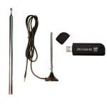
  • Comes with 2 x telescopic antennas. 1 x 9.5 cm to 31.5 cm telescopic antenna and 1 x 20 cm to 1.5 m telescopic antenna. Great for beginners to receive a wider range of frequencies without buying extra antennas.
  • No IR LED. The IR LED is useless for SDR operation and the long legs on the LED may pick up interference.

We currently have two options for sale that are shown below. The dongle only unit is perfect as a replacement dongle or for those who just want to try out the R820T2 chip. The unit with the two telescopic antennas is great for beginners who don’t have any good antennas already.

We also have limited quantities of some MCX male to various female adapter sets for sale which work out to be much cheaper than when buying them individually. Buying a set will have you ready for almost any antenna connection you need. The pigtail adapters come with 20cm of RG316 cable and the straight adapters don’t use any cabling.

Pigtail Adapters Set
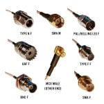
MCX -> Various Female Pigtail Adapter Set – $19.99

Straight MCX Adapters Set
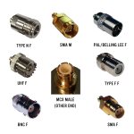
Click here to buy a MCX -> Various Female Straight Adapter Set – $16.99

Currently because of the way Amazon works, we can only ship to US customers, but we may ship overseas in the future. Shipping from Amazon is fast and free if you spend over $35 or are a Prime member. Returns from faults are also easy and welcome. If you are overseas and can’t buy from us, the alternatives for R820T2’s are the Nooelec R820T2 (US shipper), the Cosycave R820T2 (ships from Channel Islands, UK) and there are also some Chinese R820T2 (Chinese shipper) models available on ebay.

We also offer unofficial support over on our forums. If you do buy from us we hope that you will consider leaving a product review on the Amazon page as that will really help us out as small time Amazon sellers.

As an added bonus, we will also have our e-book on sale from January 16 to January 23 at $6.99 USD, reduced from $9.99 USD.

We also performed some simple performance tests on the R820T2 which we show below.

R820T2 Tests

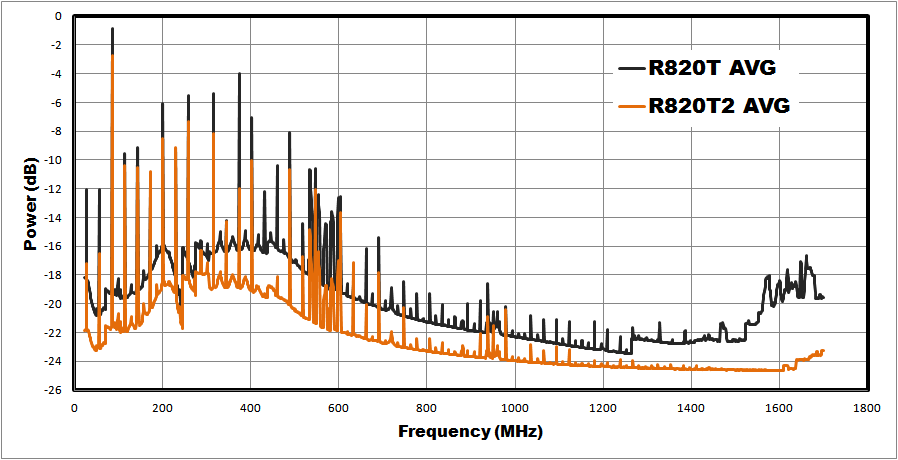
The first test was a noise floor test. We used rtl_power and ran a noise test with maximum gain and a 50 Ohm terminator connected for 15 minutes over the entire receivable frequency band. We averaged the results over three different R820T dongles and three R820T2 dongles to remove dongle to dongle variances. The results show that noise floor on the R820T2 is around 2-3 dB lower at most frequencies.

R820T2_NoiseFloor

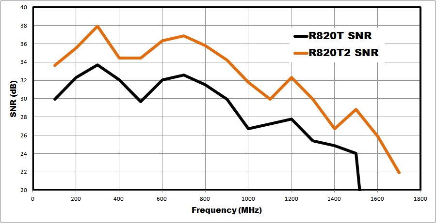
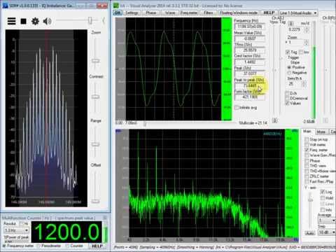
Next we tested the SNR with the gain set to zero using a HackRF as the signal source. The results show that the R820T2 is about 2-5 dB more sensitive depending on the frequency. Also, compared to the R820T, the sensitivity seems to be significantly better at 1.5 GHz to 1.8 GHz as all tested R820T units could not even detect the test signal above 1.5 GHz without increasing the gain.

R820T2_SNR

Oliver Jowett HF Driver Test

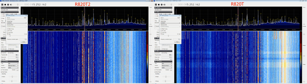
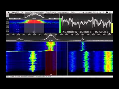
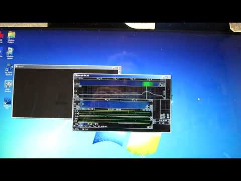
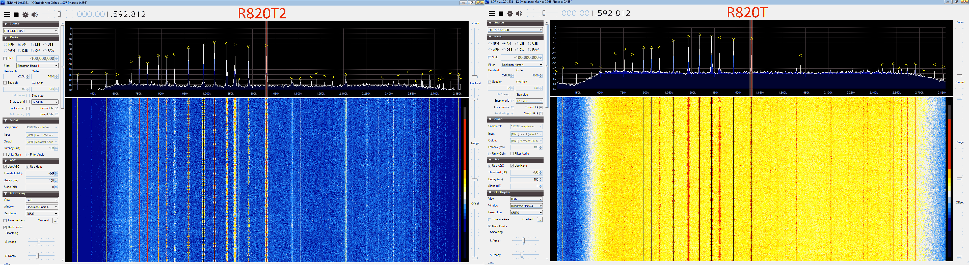
The R820T2 should have better performance at HF frequencies when using the experimental Oliver Jowett drivers. We tested an R820T and R820T2 on broadcast AM reception. At broadcast AM frequencies the R820T starts with a very high noise floor after starting it for the first time, but after about 5 minutes seems to settle down to a lower noise floor shown in the right image below. In comparison the R820T2 starts at a low noise floor almost immediately. We are unsure why there is a settling time in the first place. Even after the settling time the R820T2 had better reception and SNR as shown in the comparison image below. Both dongles were set to the second highest gain setting.

R820T2vR820T_BAM

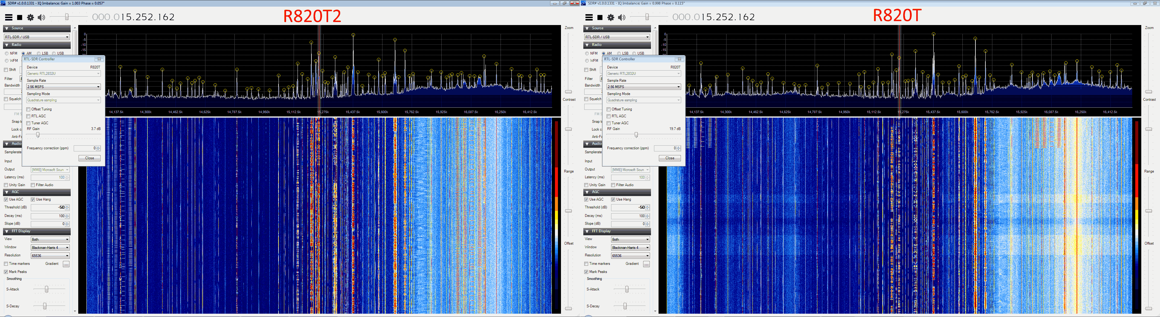
At 15 MHz international broadcast AM can be clearly heard with Oliver’s drivers. The R820T2 gets clear reception with a very low gain setting, whilst the R820T can obtain similar SNR with a higher gain setting. Though with a higher gain setting used on the R820T more noise seems to appear as can be seen in the comparison image below.
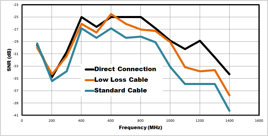
R820T2vsR820T_14MHz

Low Loss Coax

We also tested the low loss coax cable used in our RTL-SDR Blog branded antenna bases and found that it had approximately 3 dB less loss compared to the standard cable when used at most frequencies above 100 MHz. The test used a 1M length of each coax, with the HackRF as the signal generator. The direct connection test used a straight MCX->SMA Male adapter to directly connect the HackRF and RTL-SDR together.

Low_Loss_Coax