An Initial Review of the RFNM Software Defined Radio
Last year the RFNM (RF Not Magic) software-defined radio was announced and opened up for pre-orders. RFNM is an SDR based on the new 12-bit LA9310 baseband processor chip, and together with either a 'Granita' or 'Lime' daughter board it is capable of tuning from 10 - 7200 MHz or 5 - 3500 MHz respectively. It is also capable of wide bandwidth - up to 153.6 MHz on a host device like a PC. The RFNM is affordable, costing US$299 for the motherboard, US$179 for the Lime board, and US$249 for the Granita board. Currently, the second production batch is available for preorder.
Recently we received our RFNM order, with both Granita and Lime boards. This is a review of our initial impressions and tests on it. Note that while the RFNM is capable of transmitting, in this review we did not test that capability.
Physical Review
The RFNM motherboard comes as a PCB with a large heatsink on the bottom and a very quiet inline fan. The daughterboards connect to the motherboard with a board-to-board connector and are secured in place via seven screws. There is another board-to-board connector for a second daughterboard to be connected, but in this review we did not test it.
On the right side there is a 4-18V DC barrel power jack and USB-A, USB-C, HDMI and Ethernet connectors. There is also a SIM card and SD card slot on the side. On the left of the board are MMCX connectors for external reference clock, and clock out. There are also various header pinouts for PPS OUT/IN, UART, I2C, GPIO and PWM. On the heatsink side there is a JTAG connector, jumpers for resetting the firmware, and pads to solder on an OCXO.
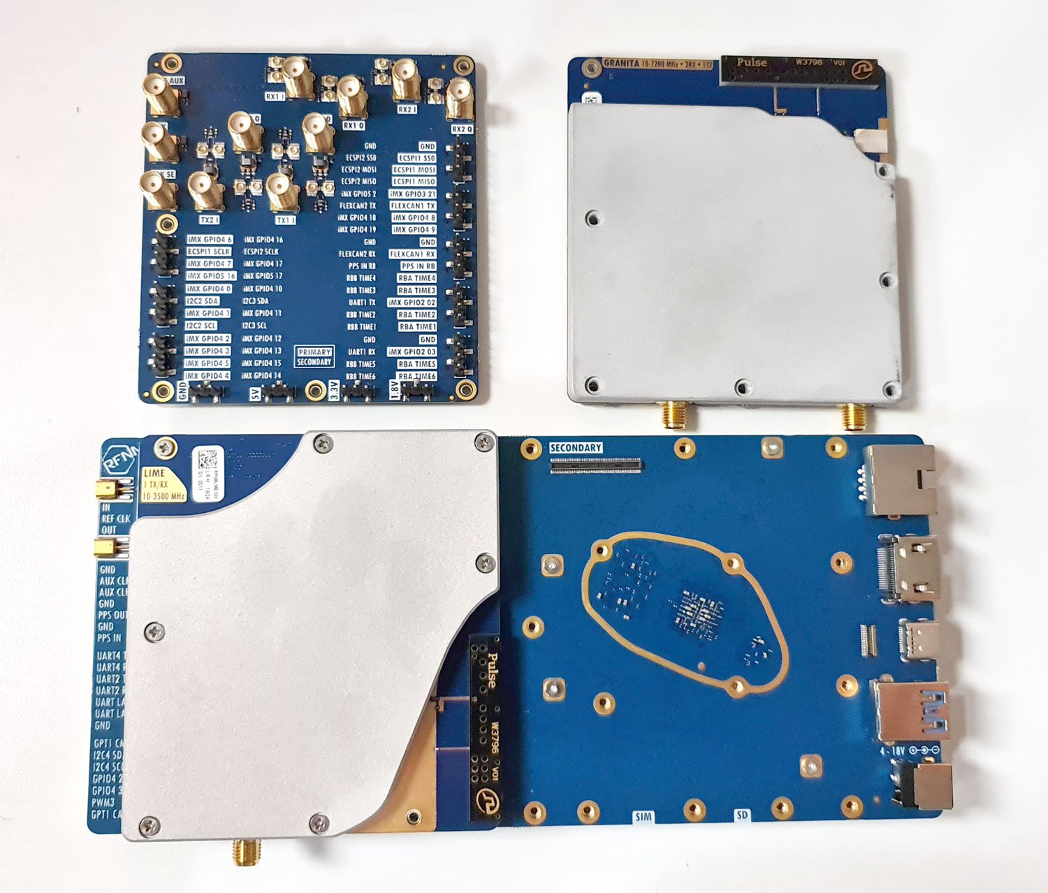
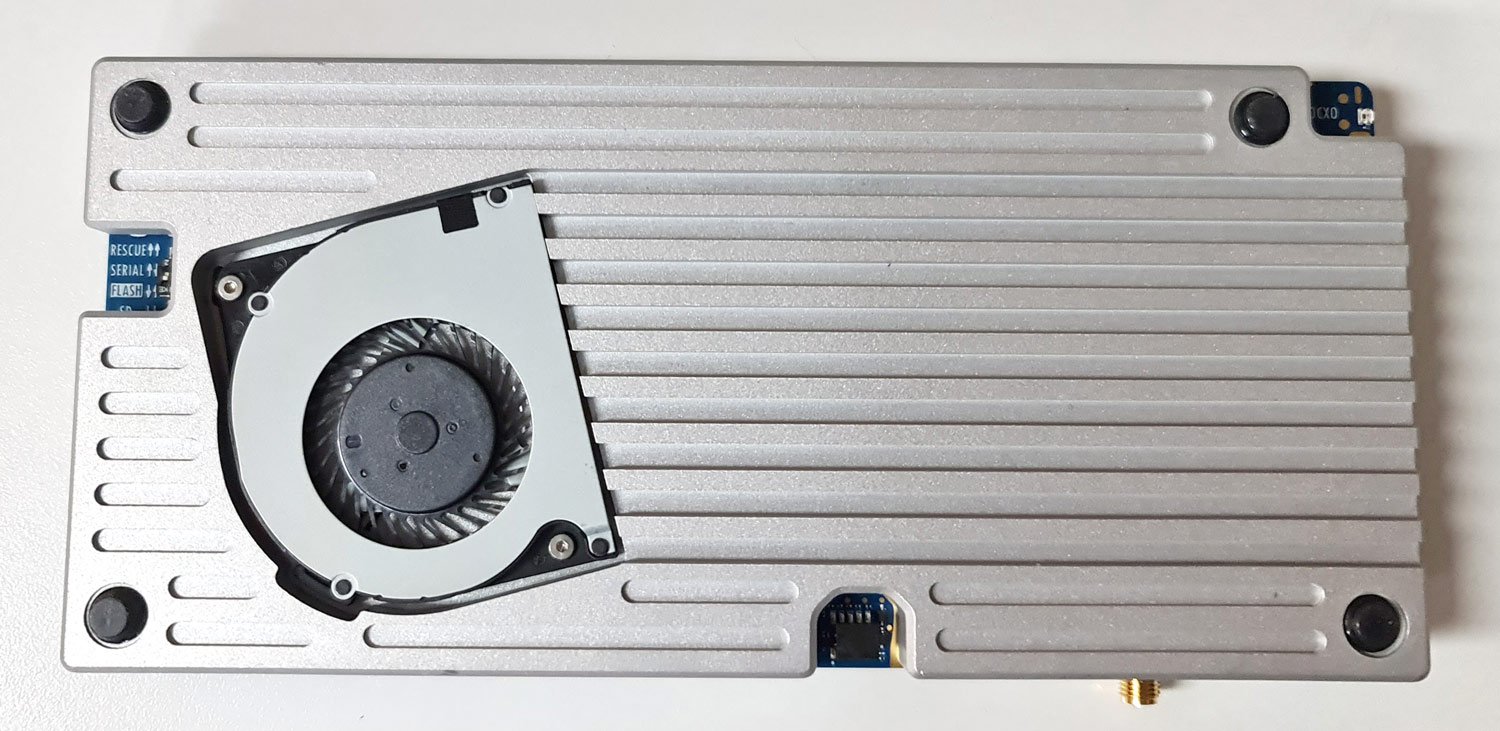
The device feels solid but there are a few exposed SMT components on the rear that have the potential to be knocked off with rough handling. All the main connectors are through-hole soldered and will not break off easily. During operation, the heatsink stays warm to the touch, and does not get too hot. The fan blades are exposed but should be safe from fingers and debris being on the bottom.
Initial Firmware Download
The device requires power from a 4 - 18V DC barrel jack and connects to a PC via a USB-C or USB-A port. According to the developer, it requires a 10-15W capable supply. In the tests below we used a 9V 2000mA switch mode supply, and a 12V 3000mA capable linear supply.
The device comes shipped without firmware, and the first setup step involves plugging in an internet-connected ethernet cable to automatically download and install the latest firmware. If you don't have an internet connected ethernet cable, an alternative is to plug in a USB stick with the latest firmware installed on it. The firmware installation took only a couple of minutes and went smoothly.
Initial Tests with SDR++
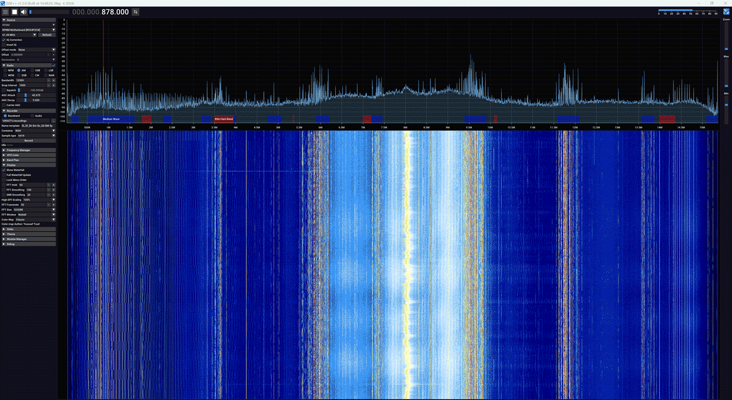
The easiest way to get something working with the RFNM is to use the custom SDR++ build included on the RFNM itself. When you plug in the RFNM it shows up on your PC as a disk drive, with an SDR++ folder. Getting started is as easy as running that SDR++ exe and clicking Play.
Initially, we encountered an issue where the RFNM wouldn't show up in SDR++, and wouldn't show up as a disk either. However, after flipping the USB-C connector it worked. This is an issue that continued throughout, and sometimes flipping wouldn't even work, but it always connected after a few reconnection attempts, and once the board was connected it was stable.
Lime Daughterboard Tests
We first tested the RFNM with the Lime daughter board. This is a board based on the Lime LMS7002 chip which is the same chip used in the LimeSDR. Here only the IQ output of the Lime chip is used, not the ADCs.
At this point, it's important to note that software support for the RFNM is still in the very early stages and SDR++ currently has no gain controls implemented. SDR++ is third-party software to RFNM so it's not any fault of the RFNM team. (NOTE: In the last few days after having already written this review, there have been several commits to SDR++ regarding RFNM, so this may already be resolved)
However, it is possible to SSH into the Linux OS system running on the RFNM system and change the gain setting through a bash command. To connect to SSH a network-connected ethernet cable needs to be connected to the board (alternatively you can use the UART port on the side of the board with an adapter). Once logged in via SSH we can browse to "/sys/kernel/rfnm_primary/rx0" and edit the value in the 'gain' text file. Then to activate the changes, simply set the value in the 'apply' text file to 1. This allowed us to optimize the gain settings for best reception.
cd /sys/kernel/rfnm_primary/rx0
echo 30 > gain && echo 1 > apply


With the ability to set the gain, the Lime board works great. Signals are strong in the VHF and UHF bands where sensitivity is approximately -135 dBm, and there is little sign of imaging with appropriate gain settings. In the 2.4 GHz band, the sensitivity remains good at around -130 dBm too. Although the advertised max frequency range is 3500 MHz, we were able to receive up to about 3.85 GHz with reduced sensitivity.
On HF, however, the Lime board performs very poorly. We start to see a drop off at around 50 MHz where the sensitivity is roughly -93 dBm, at 30 MHz about -58 dBm, and 15 MHz about -37 dBm.
Granita Daughterboard Tests
In the second test, we removed the Lime board from the RFNM motherboard and installed the Granita daughterboard. The Granita daughterboard is based on an Arctic Semiconductor 'Granita' chip, an RFFC2071A mixer, and several preselectors.
Unfortunately, we are very disappointed in the performance of Granita as there is very significant imaging of signals, and this wipes out the ability to cleanly receive almost every band. According to Davide, this problem is a firmware issue with the Arctic Semiconductor Granita chip that can maybe be fixed in the future, but there is no guarantee that it is fixable, as any fix is at the mercy of the Arctic Semiconductor, who don't seem to be very responsive to the issue. Davide (creator of the RFNM) writes:
In the Lime board, the IQ LPF works properly. For granita, it doesn’t work at all, like the -3 dB point of the 20 MHz LPF option is 100 MHz+. The manufacturer of the RFIC kept saying that this is a firmware bug, so I gave them a devkit to replicate, but they never fixed it over the last month. I don’t know at this point if this is a software problem or if they discovered it’s something more.
We confirmed that adjusting the gain settings on Granita did not help with the imaging problem either.

We also noticed that Granita was picking up or internally generating significant noise spikes. We initially assumed this was from the 9V SMPS, but even with a 12V linear power supply similar spikes were seen. The same noise was not visible with the Lime board.

Sensitivity in the bands above 600 MHz was good, at around -135 dBm. Below 600 MHz where the mixer is used, sensitivity was a bit poorer at around -123 dBm. The highest frequency we could receive was around 5900, but after about 5 GHz signals started to become very weak. The Granita board is advertised as receiving 10 - 6300 MHz, however, the documentation notes that the current batch is only capable of tuning to around 5 GHz. They note that the next batch should reach 6.3 GHz.
The Granita board was able to receive broadcast AM, shortwave, and ham frequencies with good signal strength. At 15 - 50 MHz the sensitivity is roughly -115 dBm.
At the time of this review, we cannot recommend that anyone purchase the Granita board unless they are working in a very controlled environment. We hope that in the near future the IQ LPF problem can be fixed to make the Granita board usable.
GNU Radio Tests (Windows)
The file drive on the RFNM also comes with a Soapy driver available. We copied the RFNMSupport.dll file from the RFNM drive over to our GNU Radio radioconda installation's SoapySDR folder at C:\Users\proje\radioconda\Library\lib\SoapySDR\modules0.8. Then we opened GNU Radio and opened the gnuradio_example.grc file. This brings up a FFT and waterfall display like in SDR++ and with the Gain controls exposed. With the gain controls exposed the Lime + RFNM combination works great.
The daughterboards also have built-in antennas that can be switched in or out using a drop down box in the GNU Radio UI. The built-in antenna on both boards is a Pulse W3796 which has an advertised range of 698 MHz to 2.7 GHz. While the built-in antenna works well for nearby bench reception, we preferred to still use our outdoor dipole antenna for better reception.
153.6 MHz Bandwidth Mode
It's possible to set the RFNM to provide even more bandwidth by connecting two USB cables to the PC. That gives us up to 153.6 MHz of 12-bit data. Enabling this mode requires editing a variable via the terminal
echo 153 > /sys/class/i2c-dev/i2c-0/device/0-0050/rfnm_set_dcs_freq && reboot
Once this was set we were able to edit the samp_rate block in the GNU Radio example, and set it to 153.6 MHz. At the moment the current SDR++ does not support the 153.6 MHz sample rate.

Conclusion
It's clear that the RFNM is cutting edge, yet affordable, and has great potential and excellent features and specifications. The built-in processor, DSP and GPU capabilities on the RFNM could be game changers in the near future. However, at the time of this review, the software support is still in its very early stages, documentation is lacking, and it's not yet recommended for mainstream users who just want to plug in and get started with an SDR for listening and decoding signals.
Regarding the Granita daughterboard, we would probably hold off on purchasing this until there is some clarification on the IQ LPF fix.
If you are an advanced SDR user who is comfortable with GNU Radio, Linux and advanced applications like setting up and running mobile basestations, then the RFNM may be a good choice. We are looking forward to applications that make use of the onboard DSP and GPU capabilities.