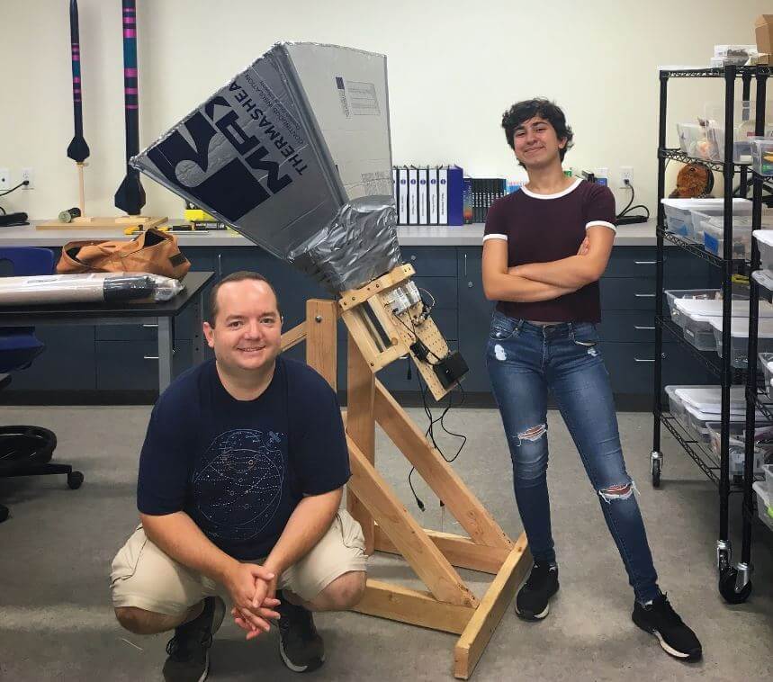
Briefly, their build consists of a horn antenna and reflector designed for the 1,420.4 MHz Hydrogen line frequency. The horn is built out of a few pieces of lumbar, metallic house wall insulation sheets and aluminum tape. The feed is made from a tin can and piece of wire. In terms of radio hardware, they used an Airspy SDR, GPIO labs Hydrogen Line Filter + LNA, and 2x Uputronics Wide band preamps, and a Minicircuits VBF-1445+ filter. For software processing, they used a GNU Radio flowgraph to integrate and record the spectrum.
The results show that they were able to achieve a good hydrogen line peak detection, and they were able to measure the galactic rotation curve doppler shift, and tangent points which prove that we do in fact live in a spiral galaxy.
The Finished Hydrogen Line SDR Based Horn Radio Telescope Antenna
Over on YouTube TechMinds has uploaded a video showing how to use the Iridium Toolkit software to receive data and audio from Iridium satellites with an Airspy. Iridium is a global satellite service that provides various services such as global paging, satellite phones, tracking and fleet management services, as well as services for emergency, aircraft, maritime and covert operations too. It consists of multiple low earth orbit satellites where there is at least one visible in the sky at any point in time, at most locations on the Earth.
The frequencies used by the older generation Iridium satellites are in the L-band, and the data is completely unencrypted. That allows anyone with an RTL-SDR or other SDR radio to decode the data with the open source Iridium Toolkit. If you're interested in how Iridium Toolkit was developed, see this previous post about Stefan "Sec" Zehl and Schneider's 2016 talk.
In the video Tech Minds shows decoding of various data, including an audio call and the satellite tracks and heat map of Iridium satellites.
Thank you to Nils Schiffhauer (DK8OK) for submitting an article documenting his tests on the Airspy HF+ Discovery (pdf mirror). Spurred on by discussions on the SDR-Console mailing list, Nils went looking for issues with spurious signals generated by the HF+ itself. In the end he finds some minor spurious signals, but notes that they have absolutely no adverse effects once an antenna is connected.
Youssef Touil (developer of the Airspy HF+ line of products) has also noted that the minimum discernible signal (MDS) of the HF+ is so low that it's become normal for very weak spurs to now be visible without an antenna connected. However, once an antenna is connected the natural atmospheric noise floor which is much higher than the MDS hides these spurs, and so the spurs have no consequence on reception.
In Nils' first test he uses a very high end Winradio W65DDC SDR to detect the spurs coming from an Airspy HF+, Airspy HF+ with preselector retrofit, and the Airspy HF+ Discovery. The results are quoted below:
[With the Airspy HF+] you indeed see a very few spurious signals, all well below -140 dBm/Hz.
With the Airspy HF+ Preselector connected, the number of spurious signal is very much reduced, as is their maximum level.
This picture still further improves with the Airspy HF+ Discovery connected: all visible seven spurious signals are measured to well below -150 dBm/Hz.
The first result is clear:
Airspy has improved also the spurious signals from model to model, landing at a stunning reduction with their matchbox-like Discovery.
The spurious signals were significantly reduced in both numbers and level.
Together with sensitivity and dynamic range, the performance of these SDRs is exceptionally good. If you see their price tag, they are a real bargain.
Overall: they deliver professional performance in every important aspect at an incredible low price.
In the second test Nils tunes to the center of a spur, then tested with a dummy load and then antenna connected. His results showed that all spurs disappeared once an antenna was connected. He summarizes below:
Yes, there are a very few and low-level spurious signals at all Airspy’s receivers – as they are found [much] worse at some competing SDRs.
By development, even this has been significantly improved from model to model with the new Discovery leading the gang.
All spurious signals disappear with an antenna connected.
There has been found no case where, in practice, any spurious signal even remotely touched or even limited reception of the most miniscule signals.To complain about “spurious signals” simply is “Much Ado about Nothing” in an Ivory Tower, far away from any practical application.
Nils also tested 7300 kHz reception and the co-existance of weak amateur radio signals with strong broadcast signals.
Last week we posted about Oona Räisänen's ([Windytan] and @windyoona) project to capture live video from her 1985 Nintendo Entertainment System (NES) using an Airspy SDR. In order to avoid expensive Video Capture cards which didn't work on her Mac, she used an Airspy SDR to decode the PAL composite video output of the NES. Last week she had black and white video working.
This week she has full color working, and has on her blog posted a write up about her project with the Airspy and her experiences with trying to find a suitable capture solution. She also goes into some detail about the CPU performance considerations of this solution, noting that there are some performance bottlenecks. She's also uploaded a video showing the results in action.
GOES 16/17 and GK-2A are geosynchronous weather satellites that transmit high resolution weather images and data. In particular they are far enough away from the earth to be able to take beautiful 'full disk' images which show the entirety of one side of the Earth. As these satellites are in a geosynchronous orbit, they can be counted on to be in the same position in the sky at all times, so no tracking hardware is required and images can be pulled down constantly throughout the day without having to wait for a polar orbiting satellite to pass over like you would with the NOAA APT or Russian Meteor satellites.
With a low cost WiFi grid dish antenna, LNA and RTL-SDR dongle, any home user within the footprint of one of these weather satellites can receive and decode live images directly from the sky. Setting up a station is overall not too difficult, but it can be a bit fiddly with a number of steps to complete. Below is our comprehensive guide. We'll show how to set up a self contained Raspberry Pi based system with goestools (free), as well as a guide for the Windows PC software XRIT decoder (US$125).
We've attempted to make the tutorial as newbie friendly as possible, but we do need to assume basic RF knowledge (know what antennas, SDRs, coaxial, adapters etc are), basic Linux competency for the goestools tutorial (using the terminal, using nano text editor), and basic Windows competency for the XRIT decoder tutorial (unzipping, editing text files, running programs).
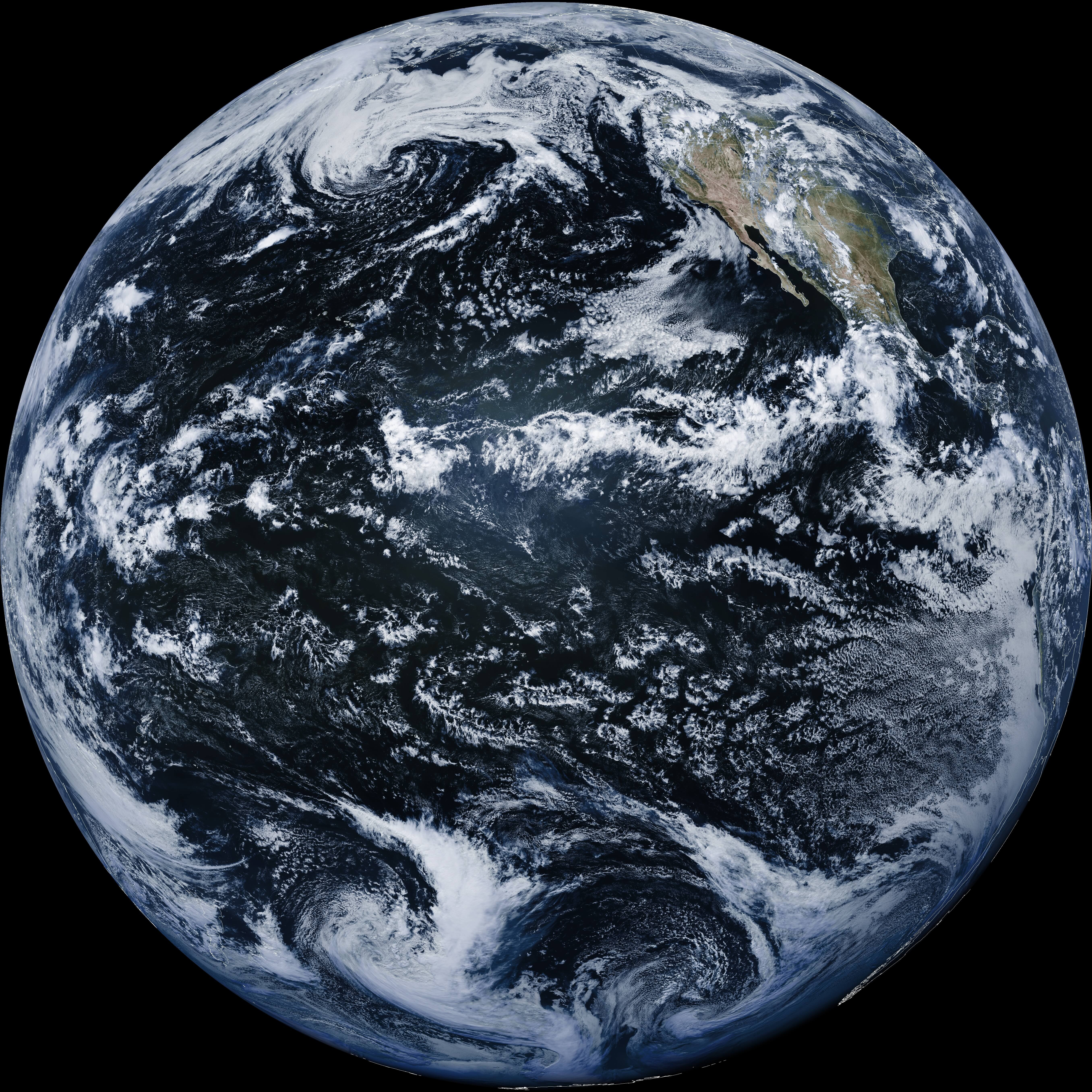
A full disk false color image received directly from the GOES-17 satellite with an RTL-SDR. Click for the full size image (14MB).
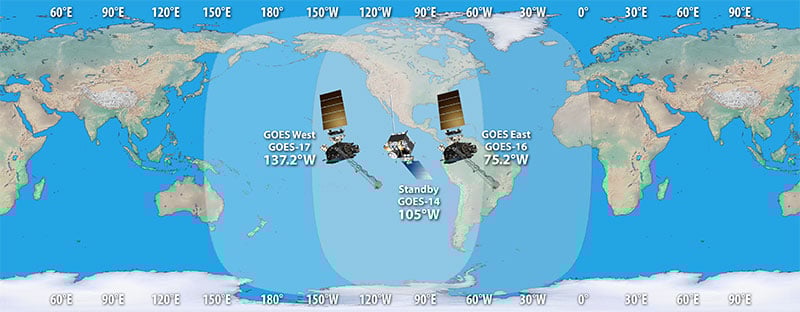
There are two fourth generation NOAA GOES satellites that are currently active, GOES-16 and GOES-17. These transmit HRIT signals, and also transmit shared data from the older third generation GOES 15, and Japanese Himiwari8 satellites. At the moment GOES-16 and GOES-17 are producing full disk images every 30 minutes, and close up "mesoscale" shots of the USA every ~15 minutes. GOES-16 (aka GOES-R) and GOES-17 (aka GOES-S) are also known as GOES-EAST and GOES-WEST respectively. At least one of these satellites can be received from North/South America, Canada, Alaska/Hawaii, New Zealand, Eastern Australia and some pacific islands.
There is also the older generation GOES-15 and GOES-14 which have been placed in standby orbits. These transmit LRIT signals which provide images at a slower rate.
GOES 16/East and GOES 17/West Signal Footprint
There is also the Korean GK-2A (GEO-KOMPSAT-2A) satellite which is very similar to the GOES satellites. GK-2A covers countries like India, Asia, Australia, New Zealand and parts of Russia. Note that you may have previously heard of the COMS-1 satellite which used to cover this area. Since July 2019 COMS-1 was replaced by GK-2A. Unlike GOES, GK-2A images are encrypted. However it has been found that "sample" encryption keys found online in demo code work just fine.
GK-2A contains both LRIT and HRIT channels, but at the moment only the LRIT channel can be decoded with the currently available software. The LRIT channel sends full disk IR images every 10 minutes in 2200 x 2200 resolution. Compared to the 5424 x 5424 resolution GOES full disk images, this is smaller, but still large enough to be interesting.
Note that even if HRIT decoding is added by the current software, you would require an Airspy or other wideband SDR as the GK-2A HRIT signal bandwidth is 5 MHz. Also since the HRIT bandwidth is so wide, the signal strength is reduced, meaning that you'll need a larger dish. People who have received the HRIT signal note that a 3M+ sized dish seems to be required.
GK-21 (GEO-KOMPSAT-2A) Footprint
You might ask why bother receiving these satellite images directly, when you can get the exact same images from NOAA at https://www.star.nesdis.noaa.gov/GOES/index.php. Well, you might want to set up your own station to be independent from the internet, or you live in a remote location without internet, or maybe just for the fun and learning of it.
To set up a receiver for GOES 16/17 HRIT or GK-2A LRIT you'll need to purchase a dish antenna such as a cheap 2.4 GHz WiFi antenna, an RTL-SDR, GOES LNA, and a Raspberry Pi if using goestools, otherwise a Windows PC can be used. The total cost could be anywhere from $150 - $200 depending on what pieces you already have available.
Before we start the tutorial, you might want to use an augmented reality Android app like "Satellite-AR" to get a rough idea of where either GOES 16/17 or GK-2A (GEO-KOMPSAT-2A) is in your sky, and if receiving them is even feasible for your location. You'll need to find an area on your land where you can mount a small satellite dish with an unobstructed line of sight view to the satellite (no trees or buildings can be blocking the signal path). If the satellite is low on the horizon (below 25 deg elevation), then things get a little more difficult as you have more obstructions and a weaker signal. But it can still be done, and we're able to routinely get good results at 24.5 deg elevation.
Note that for Europe and Africa, unfortunately there are no satellites that can be received easily with an SDR and LNA. But you might instead be interested in the EUMETCAST service, which can be received from EUTELSAT 10A (Ku band), Eutelsat 5 WEST A (C Band) and SES-6 (C Band) . To receive this service you'll need a DVB-S2 receiver and a satellite dish with appropriate band LNB. You also need a license keys and software which all together cost €100. EUMETCAST reception is not covered in this tutorial, instead see this video.
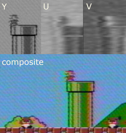
Oona (also known as [Windytan] and @windyoona) was recently looking for a way to capture PAL composite video from her old 1980’s Nintendo Entertainment System (NES) without spending a bunch of money on what are often poor video capture cards. As she already owned an Airspy SDR she decided to receive the PAL signal with the Airspy and modify some software to act as a PAL decoder.
SDR-based PAL decoder is still black & white, but after a notch filter on the audio the picture quality is getting a lot better. pic.twitter.com/SUoBlnBZF3
PAL decoding was handled via some modifications to her private Tempest software. Normally Tempest type programs like TempestSDR that we covered in a [previous article] are used to spy on computer/TV monitors from signals that are unintentionally emitted in the surrounding area.
Oona has made the connection from the composite output directly to the SDR antenna input so it’s not unexpected that you’d have a strong signal. However, I have to admit that’s an incredibly clear image for a video being demodulated via a software radio.
What makes this an even more amazing feat is that the latency is low enough that it’s nearly playable using a computer and SDR in place of a television set.
I’ve been looking for ways to capture NES video on my Mac. No easy+cheap solutions, but with some changes to my Tempest tool I can use the Airspy to receive the analog video carrier. The latency is almost good enough for playing, though it’s not my goal 🙂 pic.twitter.com/B6x44NEuvK
Over on YouTube Tech Minds has posted a video of him using an Airspy HF+ Discovery to hunt for signals like non-direction beacons (NDB's) and other morse code CW beacons. The Airspy HF+ Discovery is a new software defined radio that builds upon the already excellent original Airspy HF+.
One key improvement that many people have been experimenting with is it's improved VLF and LF capabilities, which is where most beacons are. It is capable of tuning down to 0.5 kHz (500 Hz). Over on Twitter, @prog (creator of these Airspy products) has been experimenting with simple and small ferrite loop antennas for VLF/LF and finding excellent results due to the low noise figure and good impedance matching of the HF+ Discovery.
Hunting LF/MF/HF Beacons With An Airspy HF+ Discovery
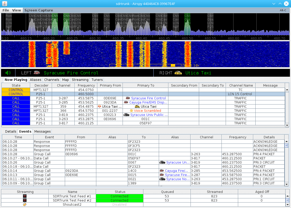
You may recall that a few years ago we released a tutorial on how to set up and use [SDRTrunk]. Fast forward a few years and the software has seen numerous changes. This application was designed primarily for tracking trunking radio systems but also has the ability to decode things like MDC-1200, LoJack and more.
The software is compatible with many Software Defined Radios such as our RTL-SDR v3, HackRF and the Airspy. Some of the newer improvements include a bundled copy of java so that an installation of java is not required on the host computer, as well as decoding improvements for P25 among other digital voice modes. You can find a full list of improvements along with the latest release on [GitHub]
The biggest feature many have been waiting for is the ability to import talk groups for their radio system into the application from radio reference. While this has not yet been implemented, user [Twilliamson3] has created a [web application] that will convert table data from radio reference into a format that is supported by SDRTrunk.