Creating a Linear Transponder with an RTL-SDR, HackRF and Raspberry Pi
A linear transponder is essentially a repeater that works on a range of frequencies instead of a fixed frequency. For example, a normal repeater may receive at 145 MHz, and repeat the signal at 435 MHz. However, a linear transponder would receive a wider bandwidth, and add a set frequency offset to the received signal. For example a signal received by a linear transponder that receives from 145 - 145.5 MHz, may receive a signal at 145.2 MHz and it would translate that up to 435.2 MHz. Another signal received at 145.4 MHz would translate up to 435.4 MHz. Hence the received frequency linearly translates to the transmitted frequency.
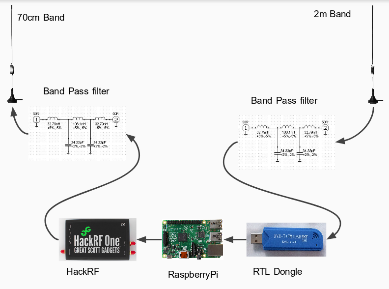
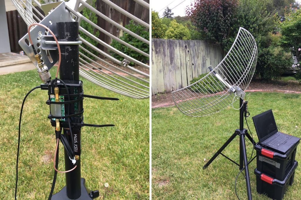
Over on his blog ZR6AIC has shown that it is possible to create a linear transponder using an RTL-SDR for receiving, a Raspberry Pi for processing the signal, and a HackRF for re-transmitting the signal. 2M and 70cm band bandpass filters are also used. For software he uses a GNU Radio flowchart that simply moves the IQ data from the RTL-SDR to the HackRF.
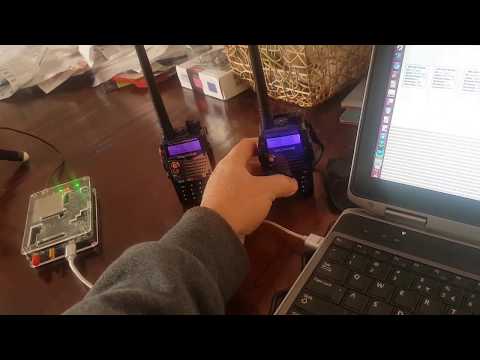
In the video below he demonstrates the linear transponder in action with two handheld radios.