CENOS Launches Affordable And Easy-to-use Simulation Software For Antenna Design
Over the past few months we have posted a few times about the beta of CENOS, a new antenna modelling and simulation design package. Recently CENOS has exited it's beta testing phase, and they have put out a press release about the first release.
Of most importance is that the software is affordable for hobbyist's, with a 10-day free trial and subscription price of €20 (US$25) per month for hobbyist use (no live engineering support).
Electromagnetics simulation software company CENOS (Riga, Latvia) continues on its mission to democratize simulation software by releasing its newest application designed for radio frequency and antenna design engineers. CENOS released its first electromagnetics simulation software focused on the induction heating applications in 2017 and it proved to be a success - mainly because of the simple and straightforward user experience and the specialization and focus on a single industry. After a year of development and testing in close cooperation with its avid beta-tester community, the Antenna Design simulation software was finally released for public use at the end of April, 2021.
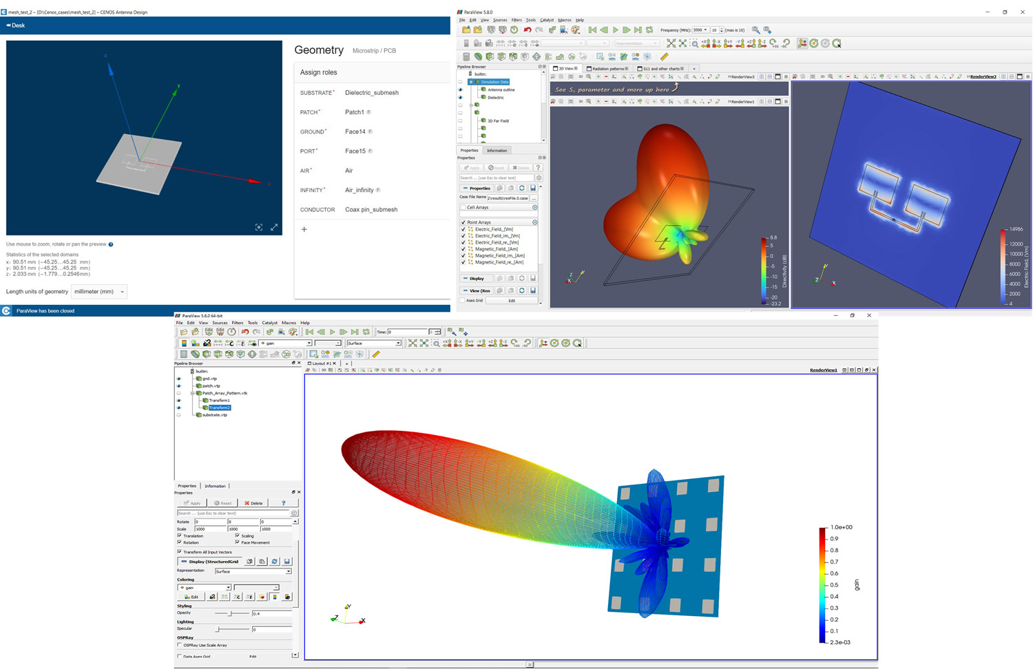
CENOS Antenna Design is an intuitive FEM-based software that helps engineers to speed up RF antenna design, it solves Maxwell’s equations directly with no simplifications or limitations. Therefore, the results provided by CENOS are accurate for wide ranges of geometries and antennas, including very complex geometries. For instance, the software is good for high Q, multi-port simulations with arbitrary 3D structures. It is specialized for the simulation of microstrip- and wire-type antennas that include various geometries (fractal, helix, horn, loop, slot, patch, spiral, and others), as well as dipole and monopole antennas.
CENOS co-founder Dr. phys. Mihails Scepanskis: “Two years ago we launched a specialized induction heating simulation software to cover the growing demand in the SME sector - smaller equipment manufacturers, tooling shops, and production plants. Following the success in the low-frequency applications, we decided to move to the microwaves with the same mission - to democratize the simulation software, make it accessible for every engineer. I believe, it is an awkward situation in the market - engineers have to choose either to pay tons of money for enterprise-type generic simulation packages to utilize just a fraction of their functionality or to use over-simplified 1D approximations with the hobbyist-level software. With CENOS we have leveraged the power of open-source algorithms to break the status quo - to deliver a full-functionality FEM software for price-sensitive business users and individuals.”
CENOS Antenna Design is free to try for 10 days, after which the users can choose from the two subscription plans - for an individual or business use, starting from 20 euros per month ($25). The business version includes the features that help to automate and speed up simulation processes and has more integrations with the existing software and, most importantly, it has a live customer support through the chat and video calls. More features are planned to be added in 2021 and thus the prices may be increased over time, so now it is a good moment to subscribe and get all the future updates for a lower price.
The company name CENOS stands for “Connecting ENgineering Open Source” highlighting the new software approach they invented. It is a platform that connects the best of community-driven open-source algorithms into one seamless user experience and since it is a desktop software - the data do not leave the owner’s computer. CENOS was founded in 2017 by 3 PhDs in physics and mathematics who committed themselves to the democratization of the simulation software by making it easy, affordable, and secure for every engineer. CENOS is a startup, funded by the leading San Francisco early-stage investor ‘500 Startups’, the leading B2B European accelerator Startup Wise Guys, and the cohort of the Baltic business angels.
CENOS offers a 10-day trial, follow the link to sign up: https://www.cenos-platform.com/antenna-design