UFO Detection with an Image Intensifier and FM Reflections Received with an RTL-SDR
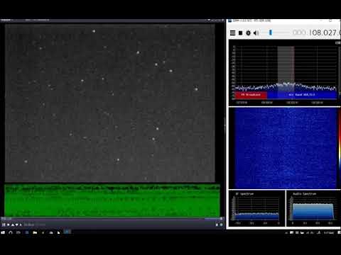
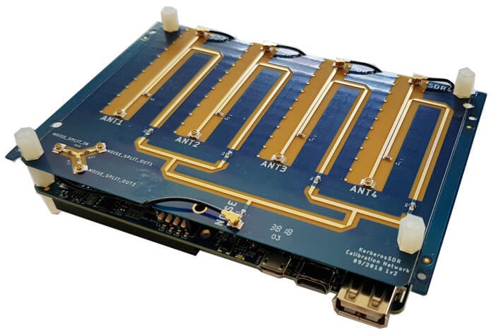
Recently reader Syed Ali wrote in and wanted to share some experiments in UFO detection that he's been performing with an image intensifier and an RTL-SDR. The RTL-SDR is used to detect a distant FM radio station reflecting from objects passing overhead, and the image intensifier is a sensitive camera that helps make events like satellite passes more visible. In his video some visually detected objects like a possible satellite pass or aircraft at 0:09 to 0:18 and 0:55 to 1:00 seem to correlate with a radio reflection.
Syed Ali writes:
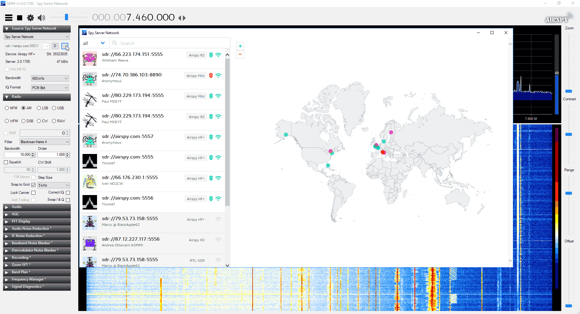
These are three small video clips taken from an hour observation. I had an idea how to use RTL-SDR for meteor detection. So I tuned my rtl-sdr to a distant FM Radio station behind a mountain range from my own location. Any object flying over mountain range can be detected by receiving the transmission of that FM radio station via its signal being reflected from that flying object.
So I set up my image intensifier pointing towards the sky in the same direction above those ranges. I recorded a few unknown objects in the video viz a viz their RF reflections and Dopplers in sdrsharp software.
You will also notice a strange laser beam which seems to be coming from the sky to the ground because it encircles and changes its position around the field of view of my image intensifier. Moreover, in the last few seconds of the clip, you will see a strange object hovering and then taking a U turn near left edge of the video frame. Those were indeed strange findings. Please see for yourself and do leave your comments. Thanks. Observation Time : 1:20 am to 2:30 am, 21 October 2018
We're a little skeptical about the UFO claims though, as the lasers may just be car headlights, and the fast moving object may just be a bug reflecting light, and the lack of radio reflections around those points seem to confirm that nothing large is there.