moRFeusQT Updates: Automatic Tracking Generator Plotting with Airspy
Outernet's moRFeus is a signal generator and frequency mixer that can be controlled either by it's built in LCD screen, or via software on a Windows or Linux PC. It can generate a clean low phase noise tone anywhere between 85 to 5400 MHz. Because it can be computer controlled it is possible to use moRFeus as a tracking generator for characterizing filters and measuring antenna SWR. A tracking generator is just a signal generator that can be set to output at the same frequency that the measurement receiver is tuned to.
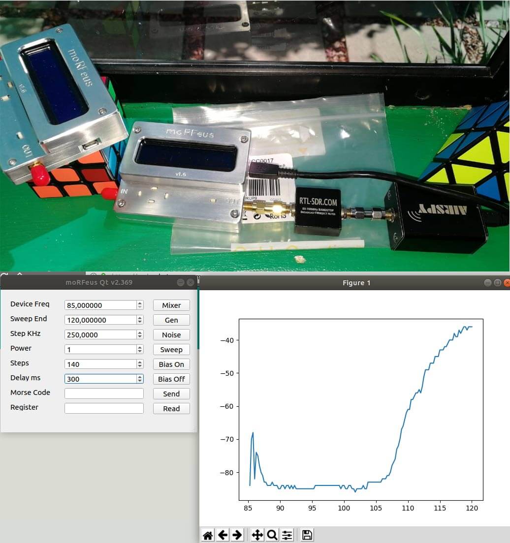
In the past we've posted about some software developed by Ohan Smit, which allows a moRFeus to be controlled on a Windows/Linux PC via a nice GUI. Recently he's updated the software and it can now draw power (dbFS) graphs for characterizing filters when combined with an Airspy and TCP comms to GQRX. Ohan writes:
So when you press sweep, it detects if there is any TCP servers on port 7356 and if so tunes the radio and gets a power measurement and after the sweep is done, morfeusqt renders a graph on the fly.
It now also supports multiple devices, no configurations required. It just opens another window for the second device.
These features thus far work on both Windows 10 and Ubuntu 18.04.1, these are my two testing environments with GQRX and the Airspy.
Ohan also notes that he's working on several new features such as the ability to plot VSWR, remote control of the moRFeus via TCP, support for multiple SDR TCP protocols such as rtl_tcp, soapytcp etc, threading and progress bars, as well as possibly support for cheap Osmo-FL2K devices as a tracking generator.
You can follow his developments live on the Outernet forums.