Over on YouTube Ian Grody has uploaded two videos demonstrating an early alpha project that he is working on which combines Android Tasker with RTL-SDR frequency scanning. Tasker is an Android automation app which allows users to define a task based on a context. For example, you could set it to turn on WiFi and open an app (task) every time you arrive at a certain location (context).
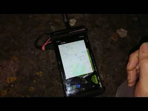
Ian's idea is to create a Tasker application that performs an rtl_power scan with the RTL-SDR whenever a certain context is detected. The current version of his Tasker app can perform an rtl_power scan over a certain frequency range at the tap of a button, detect the strongest frequencies in that range, and plot a marker at the current location on a Google map which displays the strongest frequency detected at that location. He eventually hopes to turn the application into a wardriving application that will scan 27 MHz - 1.7 GHz for active signals while on the move.
Thank you to Agrosi Luciano for submitting news about his new RTL-SDR compatible Android App called "IGate2". IGate2 is a receive only APRS IGate written for Android devices. There is a free and paid version of the app. The free version is limited to 100 packets forwarded per session. The paid version costs US$3.49 and has unlimited packet forwards. The description of the app is pasted below:
The RTL-SDR dongle tuner (cost starting from 10 €) and its antenna, receives the information contained in APRS packets transmitted from HAM radio stations, and then a phone device, with IGate2, forwards them to the world wide web using its internet connection (WiFi or 3G).
IGate2 acts as a Software Defined Radio Demodulator, a TNC Modem and an Internet Gate.
If you already own an unused cellular phone or tablet, IGate2 represents a very cheap, compact and easy-to-use solution for suppling an IGATE service to radio amateur community.
Raw data contained in radio packets are visible on the phone screen and may be routed (if you check this option) to the APRS-IS network. All data convoyed and shared in APRS-IS network can be seen in maps and bulletins on particular websites, for example: http://aprs.fi/ .
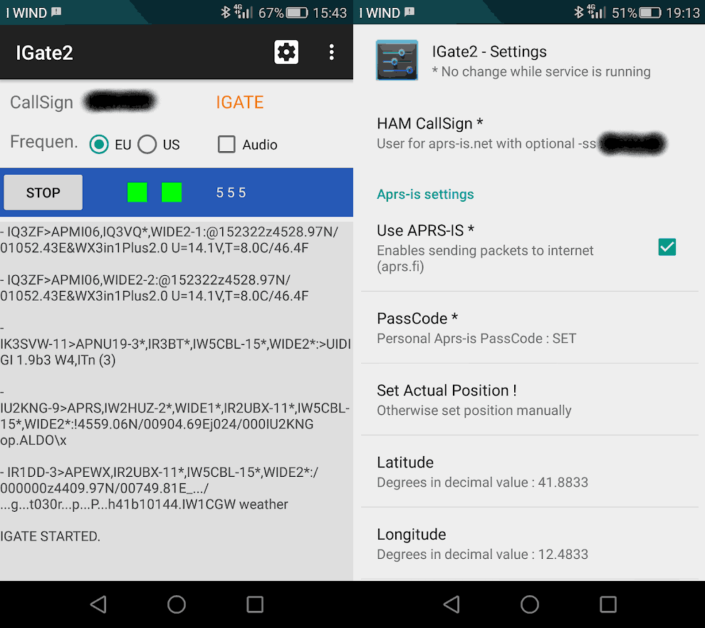
To be authorized to send data to APRS-IS you must have a HAM CallSign and a PassCode. See aprs-is.net. If you are not a radio amateur, you may only use your equipment in receive only mode. The app has an audio monitor useful for tuning the parameters of the Sdr receiver (it may not work well in old devices with low memory). In the main page there is a frequency switch, a hub with the text of received packets, two indicator lights: one for the Sdr connection and one for the Aprs-Is connection, three counters reporting the number of: received, forwardable and forwarded packets. When you leave the main page while the IGate is running, the app service will continue working in the background, you can recall the main page by tapping the service icon in the android status bar.
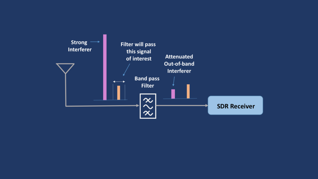
Since the device and the Sdr dongle drains much power from the phone battery, it is recommended to use the phone charger or a power bank. You will need an OTG power cable. It is not easy to find a working cable, maybe you can do it yourself. The reception quality of the IGate depends, above all, on the antenna connected to the Sdr dongle. With very strong FM broadcasts in your area, it may be helpful to manually adjust the gain of the receiver or use a band-stop filter.
If you weren't already aware, Automatic Packet Reporting System (APRS) is a digital VHF mode used in amateur radio. It allows for packets of data to be sent to receiving nodes over a local area via RF. Typical uses for it are vehicle tracking, weather station telemetry, text messages, announcements and other wireless device telemetry like high altitude balloons. An IGate is an internet connected node which receives local APRS RF signals and uploads them to the internet, to be seen on sites like aprs.fi. TX capable IGates may also broadcast to the local RF network messages from APRS transmitters on the other side of the world.
IGate2: Android App that turns your phone and RTL-SDR into an APRS IGate.
Thank you to Mario Filippi (N2HUN, WQWL238) for submitting news about his latest article that has been published in the March 2020 edition of The Spectrum Monitor magazine. The article is titled "The ABCs of ADS-B and Airband Reception using Software Defined Radio", with the description reading:
Ever wonder about all the planes you see in the sky overhead where you live? What flight is that; where is it going; how high and how fast is it? All of these planes transmit on one frequency: 1090 MHz and you can monitor them all as Mario shows us. He tells us what receiver to use, which antenna (hint: you can build a better ADS-B antenna than you can buy), which software to use and how to assemble your own desktop virtual radar screen.
The article isn't free to access as it's published in the Spectrum Monitor magazine, however the magazine only costs $3 and contains a number of other airband related articles too.
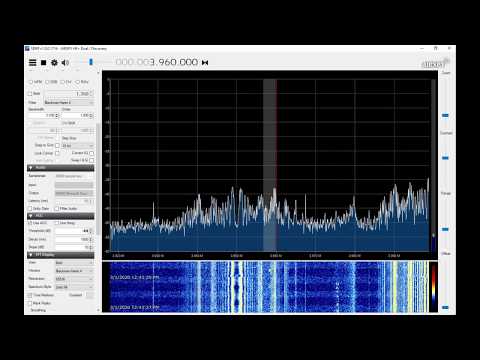
At his house W1VLF found that his solar inverter was causing huge amounts of interference on the HF bands, essentially making any hope at receiving shortwave or amateur radio signals impossible on his Airspy HF+ Discovery . However, over on his YouTube channel he's demonstrated a solution that allows him to almost completely cancel the noise.
The solution involves using a Timewave ANC-4 noise canceler, which is as analog noise cancelling device available from the manufacturer for US$209.95. To use the device you also need a noise probe which can be a small loop antenna. The noise probe is connected to the ANC-4 and placed near the source of the noise, which in W1VLF's case was just on the solar inverter enclosure mounted on the outside of his house. Then by tuning the gain and phase knobs on the ANC-4 the noise can be cancelled out of the signals received by the main antenna.
In the video W1VLF demonstrates how effective noise cancelling with the ANC-4 can be by showing the before and after results with his Airspy HF+ Discovery.
Kicking Solar inverter noise in the A$$ with noise cancelling
Over on onesdr.com a new SDR tutorial website, the authors have put up three new posts. The first post is part 2 of their "How Not to Break your Software-defined Radio (SDR) Hardware" series. This post covers mechanical strain considerations on connectors and reference clock input voltages.
The second post titled "Software-defined Radios and Bias Tees" covers the use of bias tee's and the different voltage and current specs of bias tee's on different SDRs. They explain how these specs affect which LNA's you can use, and how some bias tee's are protected against over-current damage.
Since mid-January 2020 the popular Linux and Mac compatible SDR program GQRX has seen a number of new code commits over on it's git repository. Some of the updates include moving to GNU Radio 3.8, new color maps, as well as various bug and performance fixes.
At the moment these updates only appear to be available on the latest git code, so to get them you'll need to install GQRX from source via the instructions on the git readme.
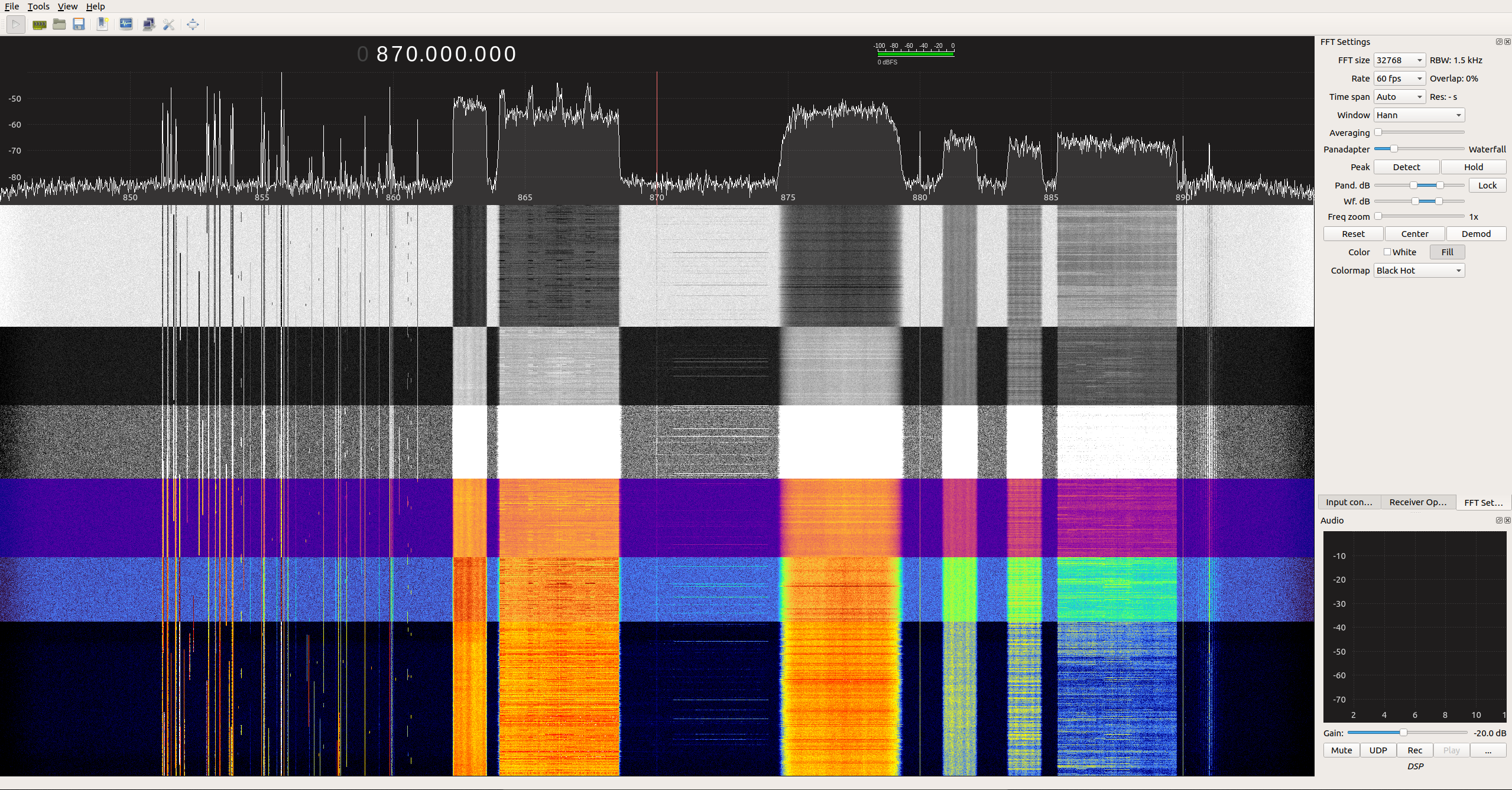
Also thank you to @devnulling for providing us with the screenshot posted below which shows off the various new color maps available for the FFT waterfall.
ADSBExchange is an aircraft tracking website service which aggregates ADS-B data from contributors running RTL-SDR's or similar receivers worldwide.
However, unlike other flight tracking sites such as flightaware and flightradar24, ADSBExchange sets themselves apart by proudly refusing to censor the tracking of military and private jets that have requested privacy. One area where this refusal to self-censor helps is with the "Dictator Alert" service. This is a service that automatically tracks the movements of private aircraft owned by authoritarian regimes via the ADS-B data collected and shared by ADSBExchange.
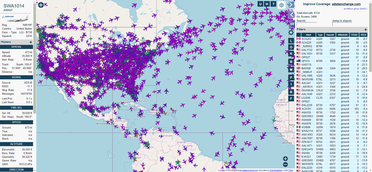
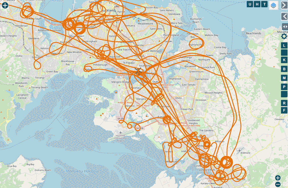
Recently ADSBExchange upgraded their web interface moving from the old Virtual Radar Server system to tar1090 which is a more fully featured open source display for dump1090. This new interface has some great features, like the ability to view the complete flight track history of any aircraft on a particular day, the ability to display only military aircraft and the ability to filter by altitude and aircraft type.
ADSBExchange.com new tar1090 interfaceViewing the historic tracks of 1-day of police helicopter activity in the new ADSBExchange tar1090 interface.
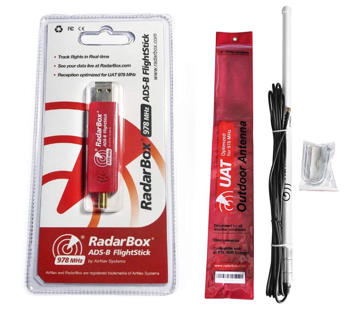
Over on Amazon we've recently seen the release of a 978 MHz UAT specialty RTL-SDR and 978 MHz tuned antenna by the flight tracking service known as AirNav RadarBox. The RTL-SDR appears to be similar to their 1090 MHz RTL-SDR version, which contains a SAW filter and LNA onboard the RTL-SDR. Due to the built in filter, this dongle will only work at the 978 MHz frequency. Like the 1090 MHz version, the dongle itself is priced at only US$14.95, and the antenna at US$49.95.
Universal Access Transceiver (UAT) is an alternative to ADS-B that is available only in the USA. It is typically used by smaller aircraft, transmits at 978 MHz, and apart from it's tracking system it has some additional advantages for pilots over 1090 MHz ADS-B, like the ability to receive alerts, weather data and radar plots. With an RTL-SDR and appropriate software these data services can also be received.
As an alternative to an RTL-SDR UAT receiver, we note that the Stratux has a hardware radio based UAT receiver available which has significantly lower power consumption. Although the receiver itself appears to be currently out of stock.
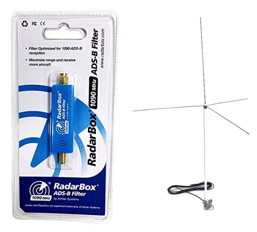
We note that we also currently have our 1090 MHz AirNav Radarbox Antenna + ADS-B optimized RTL-SDR set on sale for only US$39.95 + shipping, which is cheaper than you can find it elsewhere. Visit our store for ordering information.
The AirNav RadarBox 978 MHz UAT Optimized RTL-SDR and Antenna.New RadarBox 1090 MHz Filter and 1090 MHz & VHF Antenna single antenna.