Tagged: R820T

Video Comparison Between E4000, R820T, FC0013 and Comparison with SDR# and Linrad

On YouTube sm5bsz has uploaded a video showing a comparison between the E4000, R820T and FC0013 tuners, and also comparing the receive performance of SDRSharp and Linrad. In the video Linrad showed superior receive performance with the E4000 when compared to SDRSharp due to some custom gain profiles which are enabled in Linrad only (but can also be enabled in SDRSharp with a plugin/mod).

Note that the reason Linrad showed better performance is purely due to the fact that he used a modified librtlsdr driver in Linrad which has the custom gain profiles. However, in a previous post we posted about a modification/plugin to SDRSharp which allows this modified librtlsdr to be used, which will allow SDRSharp to perform as well as Linrad for the E4000.

Linrad is another software defined radio program which is much more difficult to use, but was the first program to support the modified librtlsdr. Some people prefer Linrad due to it’s advanced GUI which has a lot of signal information on display.

Measurements on RTL-SDR E4000 and R820T DVB-T Dongles: Image Rejection, Internal Signals, Sensitivity, Overload, 1dB Compression, Intermodulation

Over on the SDRSharp Yahoo group, HB9AJG has posted an interesting report in a PDF file containing some measurements (Note you will need to be a member of the group to download the file titled "Some Measurements on E4000 and R820 Tuners.pdf". Here is a Direct Mirror of the file.) quantifying the performance of both the E4000 and R820T RTL-SDR DVB-T dongles. See the discussion in the Yahoo group here.

These results confirm the feeling that many RTL-SDR users have had: that the E4000 is more sensitive in the lower frequencies, and that the R820T is more sensitive in the higher frequencies, which is why it is recommended for ADS-B. The results also show that the R820T is better in terms of Image Rejection and Internal Signal Birdies.

He comprehensively summarizes his results in the following

Image Rejection
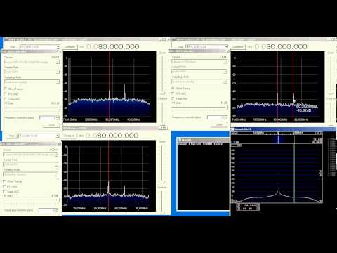
Because the E4000 is a Direct Conversion Receiver, it has an Image Rejection problem. By switching on Correct IQ in SDR# a more or less acceptable 50dBs are reached. For the same reason, a "hump" shows in the center of the spectrum display. By using a well filtered external power supply (not from the USB connector) the hump might be reduced.
  
Internal signals
The E4000 shows many signals actually not present at its input ("birdies"). Birdies are easy to recognize: most of them (except the harmonics of the clock) vary their frequency when moving the spectrum window in frequency. Many of them even move up if you move the window down in frequency.

The R820 is much cleaner in this respect: besides the harmonics of the clock (28.8MHz) only few birdies show up.

Sensitivity
Both dongles have a very high sensitivity. Between about 50 and 450MHz the E4000 is about 5dB better than the R820 (-139dBm vs -134dBm). At 1000MHz the E4000 is about 8dB less sensitive (-129dBm vs -137dBm). No measurements could be made above 1040MHz.

Overload and 1dB Compression
If a signal is strong enough, it may cause overload, i.e. many (unwanted) signals show up on the spectrum display that are not present at the antenna input. Also, if we listen to a desired signal, another signal (if strong enough) may cause a reduction of the S/N ratio of the desired signal.

Both dongles have a digitally tuned RF filter after the preamplifier that (together with the following digital signal
processing) improves the overload/1dB compression limit considerably.

- The filter of the E4000 is about +/-0.8MHz wide, but less steep than the filter of the R820.
- The filter of the R820 is about +/-3MHz wide, but steeper than the filterof the E4000.

For the E4000 the overload/1dB compression limit is not linearly dependent of the gain set in Configuration of SDR#:
if the gain is reduced by 13/20/30dB, the overload limit is improved by only 7/14/25dB (measured on 145MHz only).

For the R820 the overload/1dB compression limit is quite linearly dependent of the gain set in Configuration of SDR#: if the gain is reduced by 11/20/30dB, the overload limit is improved by 12/20/30dB (measured at 145MHz only).

For both dongles it seems there is nothing to be gained from activating RTL AGC or Tuner AGC.

Intermodulation
Intermodulation products in general show up close to the overload/1dB compression limits. However, if the strong
signal is on the roll off of the filter, they appear well before this limit.

Aliasing
Aliasing always occurs if an insufficiently band limited signal is sampled, i.e. if the signal to be sampled contains frequencies above half the sampling frequency. Thus, aliasing is an effect showing up in many SDRs, not only in these dongles. In both types of dongles there is not much space for brick wall filters. Therefore, aliasing effects are well visible with both dongles.

What do we learn from these tests?

- Both types of dongles are very sensitive. The choice depends on which frequency range you are most interested in.

- Considering internal signals and image rejection, the R820 is much cleaner than the E4000.

- Set the spectrum display of SDRSharp to show a range of not more than 60db above the noise floor. If a signal is close to the top, you know you are close to overload.

- Both types of dongles are prone to overload by strong signals within their filter bandwidth: +/-0.8MHz for the E4000, +/-3MHz for the R820. Therefore, keep signals within this bandwidth to not more than about 60dB above the noise floor
by reducing the gain. If increasing the gain does not audibly increase the signal to noise ratio of the desired signal any more, reduce the gain by one step. Do not switch on RTL AGC or Tuner AGC, as it seems there is nothing to be gained.

- Outside their filter bandwidth both types of dongles can live with much higher signals without showing serious degradation. Use the gain control as explained above to check a possible reduction of signal to noise ratio of the desired signal or the appearance of "new" signals not present at the antenna
input.

- Intermodulation occurs if several strong signals are present within the bandwidth of the dongle. Their individual power adds up (add 3dB per equally strong signal). Therefore, in frequency bands with many strong signals, e.g. broadcast bands, the gain must be reduced even further. Watch for "new" signals appearing when increasing the gain, and then reduce the gain by one step.

- If very strong signals are present at the antenna input >-40dBm), they should be attenuated by bandstop or notch filters.

Receiving a 10GHz Beacon with RTL-SDR and an Avenger LNBF

In this video YouTube user feri67000 shows reception of a 10 GHz amateur beacon over 26km using the RTL-SDR, and an ‘Avenger LNBF‘, which we believe is this one which only costs $11. The LNB within the Avenger antenna converts the 10 GHz signal into a frequency that is receivable by the R820T RTL-SDR.

F0EQE reception F5ZWZ/b 10GHZ beacon rtl sdr R820T + SAT LNB PLL Avenger

Also, in this video by YouTube user EA5KGD reception of a voice signal is shown using the RTL-SDR and Avenger LNBF.

SDR RTL 2832U E4000 RX EB5EA on 10GHz beside Avenger LNB PLL (part 1)

Receiving SSTV with RTL-SDR

Over on the Radio Antics blog fellow RTL-SDR enthusiast Andrew has been using the RTL-SDR to receive Slow Scan Television (SSTV) amateur signals. SSTV is a method ham radio enthusiasts use to send small images to one another. The images often contain their ham call sign overlaid on the image.

Andrew was able to receive several SSTV images using an R820T dongle tuned to the 27 MHz (11 meter) band. He also used a Funcube Dongle+ and got similar results.

Check out his post for some of the images he received, and his video below for an example of the receiving process.

Portable RTL-SDR Running on Raspberry Pi

Over on Reddit user olgierd has posted a video on this thread showing his work on developing a portable software defined radio based on an RTL-SDR R820T, the rtl_fm software and a Raspberry Pi with LCD screen. The software is based on rtl_fm which has the capability to demodulate FM/AM/SSB signals. His video shows him tuning to various signals using a tuning knob.

Note that his setup is capable of playing the audio, but it is not shown in the video as he only had earbuds connected. In the future he hopes to make it more portable by adding a li-ion battery.

RTL-SDR Tutorial: Receiving Weather Balloon (Radiosonde) Data with RTL-SDR

Around the world meteorological weather balloons are launched twice daily, and continuously transit weather telemetry to a ground station using something called a radiosonde. The RTL-SDR software defined radio combined with a decoding program can be used to intercept this telemetry, and display it on your own computer. You will be able to see real time graphs and data of air temperature, humidity, pressure as well as the location and height of the balloon as it makes it's ascent.

Note that if you are in the USA, then this tutorial may not be applicable for you as different radiosondes are used. Instead have a look at this post which shows how to use the SkySonde software from NOAA. You can also try an alternative command line based decoder called RS available on GitHub.

This tutorial is also applicable to other software defined radios such as the Funcube dongle, Airspy, HackRF, BladeRF or even hardware radios with discriminator taps, but the RTL-SDR is the cheapest option that will work.

Examples

In this example YouTube user Superphish shows a radiosonde being received and decoded using a RTL-SDR, SDRSharp and SondeMonitor.

Weather Balloon (Radiosonde) tracking with RTL SDR (RTL2832), Sondemonitor and SDR Sharp

Continue reading

How to Calibrate RTL-SDR using Kalibrate-RTL on Linux

YouTube user NeedSec has posted a good tutorial video showing how to use Kalibriate-RTL, a program used to determine the frequency offset error of your RTL-SDR dongle. Every RTL-SDR dongle will have a small frequency error as it is cheaply mass produced and not tested for accuracy.  This frequency error is linear across the spectrum, and can be adjusted in most SDR programs by entering a PPM (parts per million) offset value.

Kalibrate is a Linux program that uses GSM mobile cell phone base stations to determine the PPM offset, by using the GSM signals own frequency correction bursts. See the tutorial video below.