Tagged: R820T

RTL-SDR Tutorial: Analyzing GSM with Airprobe/GR-GSM and Wireshark

The RTL-SDR software defined radio can be used to analyze cellular phone GSM signals, using Linux based tools GR-GSM (or Airprobe) and Wireshark. This tutorial shows how to set up these tools for use with the RTL-SDR.

Example - Analysing GSM with RTL-SDR Software Defined Radio

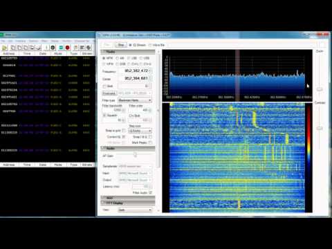
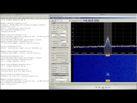
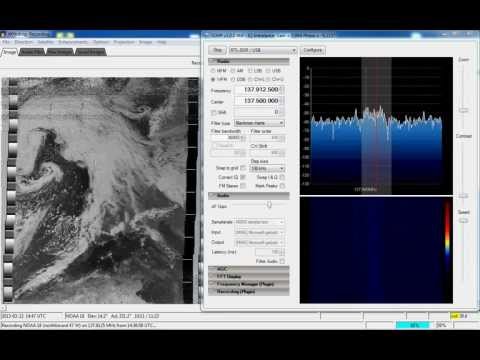
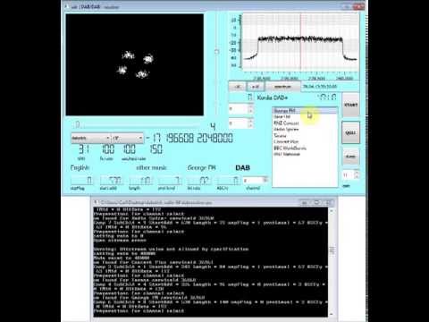
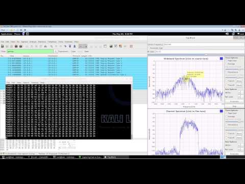
Here is a screenshot and video showing an example of the type of data you can receive. You can see the unencrypted GSM packet information. You will not be able to see any sensitive information like voice or text message data since that part is encrypted. Decryption of messages that are not your own is very difficult, illegal and is not covered in this tutorial.

Analyzing Cellular GSM with RTL-SDR (RTL2832), Airprobe and Wireshark

Kali Linux with Airprobe and Wireshark and RTL-SDR Software Defined Radio 
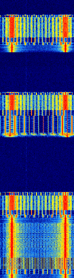
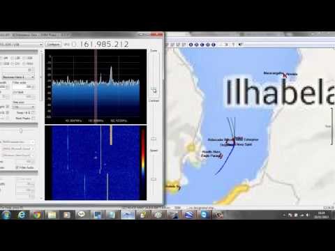
First, you will need to find out at what frequencies you have GSM signals in your area. For most of the world, the primary GSM band is 900 MHz, in the USA it starts from 850 MHz. If you have an E4000 RTL-SDR, you may also find GSM signals in the 1800 MHz band for most of the world, and 1900 MHz band for the USA. Open up SDRSharp, and scan around the 900 MHz (or 850 MHz) band for a signal that looks like the waterfall image below. This is a non-hopping GSM downlink signal. Using NFM, it will sound something like the example audio provided below. Note down the strongest GSM frequencies you can find. GSM Non Hopping Waterfall Image

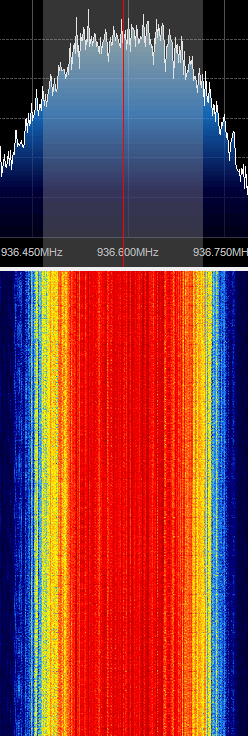
The rest of the tutorial is performed in Linux and we assume that you have basic Linux skills in using the terminal. For this tutorial we used Ubuntu 14.04 in a VMWare session. You can download the various ready to go Ubuntu VMWare images from here, and the free VMWare player from here. Note that virtual box is reported not to work well with the RTL-SDR, as its USB bandwidth capabilities are poor, so VMWare player should be used. 

Install GR-GSM

This tutorial is heavily based on the instructions from the gr-gsm GitHub readme at https://github.com/ptrkrysik/gr-gsm.

  1. The easiest way to install gr-gsm is to use Pybombs. Pybombs will automatically install gr-gsm, and all the required dependencies including GNU Radio.
    $ sudo apt-get update
    $ sudo apt-get install git python-pip
    $ sudo pip install PyBOMBS
    $ sudo pybombs prefix init /usr/local -a default_prx
    $ sudo pybombs config default_prefix default_prx
    $ sudo pybombs recipes add gr-recipes git+https://github.com/gnuradio/gr-recipes.git
    $ sudo pybombs recipes add gr-etcetera git+https://github.com/gnuradio/gr-etcetera.git
    $ sudo pybombs install gr-gsm
    $ sudo ldconfig
  2. Plug in your RTL-SDR and connect it to your VM if necessary. Run grgsm_livemon by typing grgsm_livemon at the terminal. A new window should open.
  3. In the new window tune to a GSM downlink frequency which you determined while browsing in SDR# and set the gain appropriately.
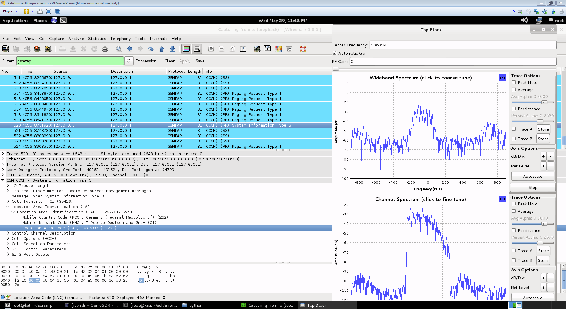
  4. Start Wireshark by using sudo wireshark -k -Y '!icmp && gsmtap' -i lo which will automatically start wireshark in the loopback mode with the gsmtap filter activated. You may get an error when opening Wireshark but this can be ignored.
  5. You should now see the GSM data scrolling along in Wireshark.

[expand title = "Old Method using Airprobe (Click to Expand)"]

Install GNU Radio

You will need to install GNU Radio first in order to get RTL-SDR to work. An excellent video tutorial showing how to install GNU Radio in Kali Linux can be found in this video shown below. Note that I had to run apt-get update in terminal first, before running the build script, as I got 404 not found errors otherwise. You can also use March Leech's install script to install the latest version of GNU Radio on any Linux OS. Installation instructions can be found here. I recommend installing from source to get the latest version. http://www.youtube.com/watch?v=B8Acp6_3DA0

Update: The new version 3.7 GNU Radio is not compatible with AirProbe. You will need to install GNU Radio 3.6. However, neeo from the comments section of this post has created a patch which makes AirProbe compatible with GNU Radio 3.7. To run it, place the patch file in your airprobe folder and then run patch -p1 < zmiana3.patch.

Install Airprobe

Airprobe is the tool that will decode the GSM signal. I used multiple tutorials to get airprobe to install. First from this University of Freiberg tutorial, I used their instructions to ensure that the needed dependencies that airprobe requires were installed.

Install Basic Dependencies

sudo apt-get –y install git-core autoconf automake libtool g++ python-dev swig libpcap0.8-dev

Update: Thanks to shyam jos from the comments section who has let us know that some extra dependencies are required when using the new Kali Linux (1.0.5) for airprobe to compile. If you've skipped installing GNURadio because you're using the new Kali 1.0.5 with SDR tools preinstalled, use the following command to install the extra required dependencies.

 sudo apt-get install gnuradio gnuradio-dev cmake git libboost-all-dev libusb-1.0-0 libusb-1.0-0-dev libfftw3-dev swig python-numpy

Install libosmocore

git clone git://git.osmocom.org/libosmocore.git
cd libosmocore
autoreconf –i
./configure
make
sudo make install
sudo ldconfig

Clone Airprobe

Now, I discovered that the airprobe git repository used in the University tutorial  (berlin.ccc.de) was out of date, and would not compile. From this reddit thread I discovered a more up to date airprobe git repository that does compile. Clone airprobe using the following git command.

git clone git://git.gnumonks.org/airprobe.git

Now install gsmdecode and gsm-receiver.

Install gsmdecode

cd airprobe/gsmdecode
./bootstrap
./configure
make

Install gsm-receiver

cd airprobe/gsm-receiver
./bootstrap
./configure
make

Testing Airprobe

Now, cd into to the airprobe/gsm-receiver/src/python directory. First we will test Airprobe on a sample GSM cfile. Get the sample cfile which I found from this tutorial by typing into terminal.

cd airprobe/gsm-receiver/src/python
wget ​https://svn.berlin.ccc.de/projects/airprobe/raw-attachment/wiki/DeModulation/capture_941.8M_112.cfile

Note: The tutorial and cfile link is sometimes dead. I have mirrored the cfile on megaupload at this link. Place the cfile in the airprobe/gsm-receiver/src/python folder. Now open wireshark, by typing wireshark into a second terminal window. Wireshark is already installed in Kali Linux, but may not be in other Linux distributions. Since Airprobe dumps data to a UDP port, we must set Wireshark to listen to this. Under Start in Wireshark, first set the capture interface to lo (loopback), and then press Start. Then in the filter box, type in gsmtap. This will ensure only airprobe GSM data is displayed. Back in the first terminal that is in the python directory, type in

./go.sh capture_941.8M_112.cfile

If everything installed correctly, you should now be able to see the sample GSM data in wireshark.

Receive a Live Channel

To decode a live channel using RTL-SDR type in terminal

./gsm_receive_rtl.py -s 1e6

A new window will pop up. Tune to a known non-hopping GSM channel that you found earlier using SDRSharp by entering the Center Frequency. Then, click in the middle of the GSM channel in the Wideband Spectrum window. Within a few seconds some GSM data should begin to show constantly in wireshark. Type ./gsm_receive_rtl.py -h for information on more options. The -s flag is used here to set the sample rate to 1.0 MSPS, which seems to work much better than the default of 1.8 MSPS as it seems that there should be only one GSM peak in the wideband spectrum window. GSM Decoding with Airprobe and Wireshark and RTL-SDR Software Defined Radio

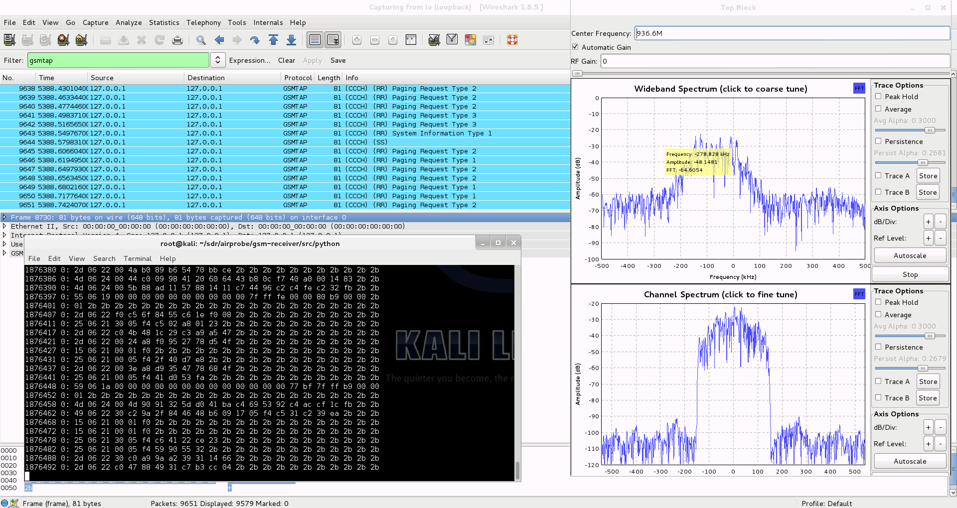
Capturing a cfile with the RTL-SDR (Added: 13/06/13)

I wasn't able to find a way to use airprobe to capture my own cfile. I did find a way to capture one using ./rtl_sdr and GNU Radio however. First save a rtl_sdr .bin data file using where -s is the sample rate, -f is the GSM signal frequency and -g is the gain setting. (rtl_sdr is stored in 'gnuradio-src/rtl-sdr/src')

./rtl_sdr /tmp/rtl_sdr_capture.bin -s 1.0e6 -f 936.6e6 -g 44.5

Next, download this GNU Radio Companion (GRC) flow graph (scroll all the way down for the link), which will convert the rtl_sdr .bin file into a .cfile. Set the file source to the capture.bin file, and set the file output for a file called capture.cfile which should be located in the 'airprobe/gsm-receiver/src/python' folder. Also, make sure that 'Repeat' in the File Source block is set to 'No'. Now execute the GRC flow graph by clicking on the icon that looks like grey cogs. This will create the capture.cfile. The flow chart will not stop by itself when it's done, so once the file has been written press the red X icon in GRC to stop the flow chart running. The capture.cfile can now be used in airprobe. However, to use this cfile, I found that I had to use ./gsm_receive.py, rather than ./go.sh as a custom decimation rate is required. I'm not sure why, but a decimation rate of 64 worked for me, which is set with the -d flag.

./gsm_receive.py -I rtl_sdr_capture.cfile -d 64

[/expand]

Going Further with Decryption

We don't cover how to decode the actual encrypted GSM data here, but this is possible to do with messages going to your own phone once you extract the encryption code for your sim card. But note that if you want to do this you'll need to put in some good study and research into understanding how GSM actually works before you can even think about trying it. Disclaimer: Only decrypt signals that you are legally allowed to (such as from/to your own cell phone) to avoid breaching privacy.

The most complete video guide is probably the YouTube tutorial by Crazy Danish Hacker, and the most complete web guide is the one by Domonkos P. Tomcsanyi available on his blog here.

A reader wrote in to let us know some information on obtaining the TMSI and Kc numbers, which are useful if you wish to go further and actually decode messages coming from your own phone. He writes:

For some reason, most of posts on the Internet concerning GSM sniffing provide very few examples of how to get our own TMSI and Kc numbers. These rely either on the BlackBerry engineering screen or the use of a SIM-card reader (see for example http://domonkos.tomcsanyi.net/?p=369). I know there are other methods like the one you describe in www.rtl-sdr.com/rtl-sdr-cell-phone-imsi-tmsi-key-sniffer/.

However, I have rarely seen anything related to the Android IMSI-Catcher Detector app. This can be easily installed via the standard repositories and it allows us to send AT commands to the modem provided we root the MS. This procedure works on many devices (I checked it on a Motorola Moto E).

Just a quick reminder of the basic AT+commands:

1. Extraction of IMSI -> AT+CRSM=176,28423,0,0,3.

2. Extraction of Ciphering Key Kc -> AT+CRSM=176,28448,0,0,9 (for SIM),
AT+CRSM=176,20256,0,0,9 (for USIM). First 16 entries.

3. Extraction of TMSI -> AT+CRSM=176,28542,0,0,11. First 8 entries.

The Android IMSI-Catcher Detector provides some additional interesting data, like the cell ID the device is connected to, the LAI, etc.

We note that software such as SimSpyII together with a Sim Card reader can also be used to easily acquire the Kc value.

If you enjoyed this tutorial you may like our book available on Amazon. Available in eBook and paperback formats.

The Hobbyist's Guide to the RTL-SDR: Really Cheap Software Defined radio.

RTL-SDR Tutorial: POCSAG Pager Decoding

The RTL-SDR software defined radio combined with SDRSharp, and a POCSAG/Flex capable decoding application can be used to decode pager messages. With this setup you can receive pager messages from all pager users on the system. If you don't know what a pager is, since they are now uncommon, here is a brief explanation from Wikipedia:

A pager is a wireless telecommunications device that receives and displays numeric or text messages, or receives and announces voice messages.

Not many people use pagers these days with mobile phone text messaging being used more, but pagers are still popular with doctors, hospitals in general, some fire and ambulance agencies and various IT companies, as they tend to be more reliable and have greater coverage. 

A Pager
A Pager

Privacy and Security

Obviously a lot of messages sent through pagers are plain text and contain personal data. Especially messages from hospitals. This is a concern as it is a major breach of patient privacy.

Security concerns also stem from the fact that many IT companies set up systems that forward notices of emails being received with the subject line visible, and system messages that contain IP addresses, email addresses and names, database error messages, and URLs.

Previously an art installation in New York was set up with an SDR to try and highlight some of the privacy and security concerns that pager use brings.

We note that in most countries it is perfectly legal to receive pager messages, as they are plain text unencrypted, but it is illegal to share or act on the information received. In some countries it may be illegal to even set up a receiver. Please research and respect your local laws before attempting this project.

Examples

Here YouTube user nerdymark shows 18 minutes of pager decoding using SDRSharp, PDW and an RTL-SDR.

18 Minutes of Pager Traffic 2012 July 12 San Jose rtlsdr sdr# pdw flex

Tutorial

While directed at the RTL-SDR, this tutorial may also be useful for use with other software defined radios such as the Funcube dongle, Airspy and HackRF, or even traditional hardware radios with a discriminator tap.

Since pager signals are usually transmitted at a very strong power, usually almost any antenna will work to receive them, even the stock antenna that comes with the dongle. Pager frequencies differ among different countries. Usually they will be anywhere from 137 - 160 MHz, around ~450 MHz, or around 900 MHz. Check radioreference.com or Google for frequencies in your area, or just search for them manually - they are usually quite easy to spot. Pagers normally use either the POCSAG or FLEX protocols, and the signals will look on a waterfall something like the signal shown below. They also have a distinctive sound when played with NFM mode. A sound sample is also shown below.

POCSAG Waterfall Image

For this tutorial, you will need to have an RTL-SDR dongle set up and working with SDRSharp. We will assume you have this much done already. If you do not, visit the Buy RTL-SDR page, and then the Quickstart guide. You will also need to have an audio piping method installed and set up. Audio piping will allow the audio from SDRSharp to be passed to a decoding program. You can use either windows stereo mixVB-cable (free) or Virtual Audio Cable (paid with trial version). 

Now, to decode the POCSAG or Flex signals, you need need to download and install a free program called PDW, which can be downloaded from this page, then follow these steps.

  1. Open SDRSharp and set the audio piping method to the one you will use under the Audio Output drop down box and then press Play.
  1. Tune to a pager POCSAG/Flex signal. Set the receive mode to NFM, filter bandwidth to 12500 Hz, filter order to 10, turn squelch OFF and filter audio OFF. Adjust the RF gain settings under the configure menu until good reception is achieved.
  1. Open PDW. You may initially receive some errors upon first opening it, but they can be safely ignored. Go to Options -> Options and Click Enable Pocsag Decoding, and ensure the 512, 1200 and 2400 boxes are all checked. Also, ensure Enable Flex Decoding is enabled and that the 1600, 3200 and 6400 boxes are all checked. Press OK.

PDW Enable POCSAG

  1. Go to Interface -> Setup. Enable the Soundcard checkbox, set the Configuration to Custom, and choose your audio piping method in the Soundcard drop down box. If you only have one audio piping method enabled in the Windows recording properties, it will automatically choose that method. Press OK.

PDW Soundcard Interface Setup

  1. Go to Monitor, and ensure POCSAG/FLEX is ticked.
  1. Now, if everything is set up correctly, the pager audio from SDRSharp should be being sent to PDW. In the top right hand corner of PDW, there should be a volume gauge. You will need to adjust the volume settings in SDRSharp, and/or the Windows volume settings so that the volume meter goes up when a pager signal is sent. The percentage shown below the gauge shows the decode error rate. If you are receiving good signals the error rate should be very low and the percentage should be at or near 100%.

PDW Decoding

Other Decoding Software

MultimonNG is a Linux based decoder which is lightweight enough to run on a Raspberry Pi using rtl_fm.

PagerMon is a app that records and displays all messages from MultimonNG in a nice web page.

Some Tips

  • Pager signals are generally very strong, and so almost any antenna can pick them up - even the stock antenna included with many dongle packages. However, if you live far away from the transmitter a better antenna matched to the pager frequency you want to monitor may be required.
     
  • If reception is very poor, you may get some garbled messages in the PDW window.
     
  • Since pagers can be so strong, you may actually need to reduce the RF gain to clearly discern between a real pager and an image. Reducing the gain may also help decoding if it is so strong that it begins overloading in the RF spectrum.
     
  • Sometimes setting the volume too loud can cause the pager audio signal to become distorted. Make sure you do not have the audio set too loud.


If you enjoyed this tutorial you may like our book available on Amazon. Available in eBook and physical formats.

The Hobbyist's Guide to the RTL-SDR: Really Cheap Software Defined radio.


ISS Packet Repeater Received with RTL-SDR

YouTube user ronpaulatemybaby has posted a video showing his reception of the International Space Station (ISS) amateur packet repeater on 145.825 MHz, using the rtl-sdr. He used a R820T dongle, two meter dipole, SDRSharp and decoding software MixW.

RTL SDR International Space Station Packet Repeater 145.825 Mhz

RTL-SDR for Budget Radio Astronomy

With the right additional hardware, the RTL-SDR software defined radio can be used as a super cheap radio telescope for radio astronomy experiments such as Hydrogen line detection, meteor scatter and Pulsar observing.

Hydrogen Line

Marcus Leech of Science Radio Laboratories, Inc has released a tutorial document titled “A Budget-Conscious Radio Telescope for 21cm“, (doc version) (pdf here) where he shows:

Two slightly-different designs for a simple, small, effective, radio telescope capable of observing the Sun, and the galactic plane in both continuum and spectral modes, easily able to show the hydrogen line in various parts of the galactic plane.

He uses the RTL-SDR as the receiving radio with an LNA (low noise amplifier) and a couple of line amps, a 93cm x 85cm offset satellite dish (potential dish for sale here, and here), and GNU Radio with the simple_ra application. In his results he was able to observe the spectrum of the Galactic Plane, and the Hydrogen Line. Some more information about this project can be found on this Reddit thread.

Here is a link to an interesting gif Marcus made with his RTL-SDR, showing a timelapse of recorded hydrogen emissions over 24 hours. Reddit user patchvonbraun (a.k.a Marcus Leech) writes on this thread an explanation of what is going on in the gif.

Interstellar space is “full” of neutral hydrogen, which occasionally emits at photon at a wavelength of 21cm–1420.4058Mhz.

If you setup a small dish antenna, and point at a fixed declination in the sky, as that part of the sky moves through your beam, you can see the change in spectral signature as different regions, with different doppler velocities move through your beam.

This GIF animation shows 24 hours of those observations packed into a few 10s of seconds.

 Marcus’ setup is shown below.

RTL-SDR Radio Telescope Setup

And here is just one of his many resulting graphs shown in the document showing the Hydrogen line.

RTL-SDR Radio Telescope Hydrogen Line

A similar radio astronomy project has previously been done with the Funcube. More information about that project can be found in this pdf file. In that project they used the Funcube, a 3 meter satellite dish and the Radio Eyes software.

However, in this Reddit post patchvonbraun explains that the Funcube’s much smaller bandwidth is problematic, and so the rtl-sdr may actually be better suited for radio astronomy.

This image is from the Funcube project document.

Funcube Radio Telescope Project

Another related project is the Itty Bitty Telescope (IBT), which does not use SDR, but may be of interest.

Meteor Scatter

Meteor scatter works by receiving a distant but powerful transmitter via reflections off the trails of ionized air that meteors leave behind when they enter the atmosphere. Normally the transmitter would be too far away to receive, but if its able to bounce off the ionized trail in the sky it can reach far over the horizon to your receiver. Typically powerful broadcast FM radio stations, analog TV, and radar signals at around 140 MHz are used. Some amateur radio enthusiasts also use this phenomena as a long range VHF communications tool with their own transmitted signals. See the website www.livemeteors.com for a livestream of a permanently set up RTL-SDR meteor detector.

In Europe typically the Graves radar station can be used for meteor scatter experiments. Graves is a space radar based in France which is designed to track spacecraft and orbital debris. If you are in Europe you can also make use of the Graves radar simply by tuning to its frequency of 143.050 MHz and listening for reflections of its signal bouncing off things like meteors, planes and spacecraft. Since Graves points its signal upwards, it’s unlikely that you’ll directly receive the signal straight from the antenna, instead you’ll only see the reflections from objects.

In other countries old and distant analogue TV stations can be used or FM transmitters can also be used.

To set meteor scatter up, simply use an outdoor antenna to tune to a distant transmitter. It should be far enough away so that you can not be receive the transmitter directly, or the signal should be weak. If you detect a meteor the signal will briefly show up strongly at your receiver. Performance can be enhanced by using a directional antenna like a Yagi to point upwards at the sky in the direction of the transmitter.

We have several post about meteor scatter available on the blog here. Read through them to get a better understanding of the ways in which it can be monitored. You may also be interested in Marcus Leech’s tutorial where he uses the RTL-SDR to detect forward meteor scatter. (doc here) (pdf here)

Pulsar Observing

A pulsar is a rotating neutron star that emits a beam of electromagnetic radiation. If this beam points towards the earth, it can then be observed with a large dish antenna and a radio, like the RTL-SDR. 

Pulsars create weakly detectable noise bursts across a wide frequency range. They create these noise bursts at precise intervals (milliseconds to seconds depending on the pulsar), so they can be detected from within the natural noise by performing some mathematical analysis on the data. Typically a few hours of data needs to be received to be able to analyze it, with more time needed for smaller dishes.

One problem is that pulsar signals can suffer from ‘dispersion’ due to many light years of travel through the interstellar medium. This simply means that higher frequencies of the noise burst tend to arrive before the lower frequencies. Mathematical de-dispersion techniques can be used to eliminate this problem enabling one to take advantage of wideband receivers like the RTL-SDR and other SDRs. The more bandwidth collected and de-dispersed, the smaller the dish required for detection.

Pulsar detection requires some pretty large antennas, and a good understanding of the techniques and math required for data processing so it is not for the beginner. See the previous Pulsar posts on this blog for more information.


If you enjoyed this tutorial you may like our ebook available on Amazon.

The Hobbyist’s Guide to the RTL-SDR: Really Cheap Software Defined radio.

Reducing Interference in the RTL-SDR

Luis Colunga has posted an interesting tip on his blog on how he reduced broadcast FM interference in the rtl-sdr dongle. He writes

Many people have noticed that even if there is not an antenna connected to the RTL SDR FM Stations still come strong. This is not good at all because these are signals that are getting into the PCB via another way that is not the antenna.

He then goes on to explain a method he used to significantly reduce the interference, which involves removing the male USB connector from the dongle PCB, and fitting your own USB cable leaving the shield floating, which he then wraps with aluminium foil.

Interference Reduction Mod

Check out the rest of his post here.

RTL-SDR Tutorial: Receiving NOAA Weather Satellite Images

Everyday multiple NOAA weather satellites pass above you. Each NOAA weather satellite broadcasts an Automatic Picture Transmission (APT) signal, which contains a live weather image of your area. The RTL-SDR dongle combined with a good antenna, SDRSharp and a decoding program can be used to download and display these live images several times a day.

This tutorial will show you how to set up a NOAA weather satellite receiving station, which will allow you to gather several live weather satellite images each day. Most parts of this tutorial are also applicable to other software radios, such as the Funcube dongle and HackRF and Airspy, but the RTL-SDR is the cheapest option. Hardware radio scanners can also work, provided the radio has a large IF bandwidth (30 kHz +) and a discriminator tap.

Note that if you have success with this tutorial, you may also be interested in decoding Meteor M N2 weather satellites which provide much higher resolution images. Also, an alternative tutorial for decoding NOAA satellites that uses rtl_fm can be found here.

NOAA Weather Satellite Image

Examples

YouTube user GaitUutLiern shows an example of receiving NOAA satellite weather images with a RTL-SDR, SDRSharp, a decoding program called WXtoImg and a QFH antenna.

Receiving NOAA weather satellite using SDR# and WXtoImg

Continue reading

SDR-J Decoding DAB Radio in Software using RTL-SDR

Digital Audio Broadcasting (DAB) is a digital method for broadcasting radio stations. The rtl dongles official driver has DAB decoding capabilities. But when the rtl dongle is used as a software radio, this capability from the original drivers can not used.

SDR-J is a SDR package for Windows and Linux which is capable of receiving FM radio and decoding DAB radio completely in software. YouTube user Superphish shows a video of SDR-J decoding and playing DAB music with a rtl-sdr dongle.

DAB Radio with RTL-SDR (RTL2832) and SDR-J

Continue reading

RTL-SDR Tutorial: Cheap AIS Ship Tracking

Large ships and passenger boats are required to broadcast an identification signal containing position, course, speed, destination, and vessel dimension information to help prevent sea collisions. This system is known as the "Automatic Identification System" or AIS for short. There are dedicated AIS receivers intended to be used on boats, or by hobbyists, but they can be expensive. A radio scanner, or the cheap RTL-SDR software defined radio (or a more advanced SDR such an Airspy) can be used to receive these signals, and with the help of decoding software, ship positions can be plotted on a map.

This tutorial will show you how to set up an AIS receiver with the RTL-SDR. Most parts of this tutorial are also applicable to other software radios, such as the Funcube dongle, Airspy and HackRF, or even regular hardware scanners if a discriminator tap is used, but the RTL-SDR is the cheapest option.

Safety Warning: This probably should not be used a navigational aid on a boat as the field reliability of the RTL-SDR or other software radios is not proven. This guide is intended for land based scanner hobbyists.

Note, tracking ships with AIS is very similar to tracking aircraft with ADS-B, which is another project that may interest you.

Examples of AIS received with RTL-SDR

An AIS radar example is shown by YouTube user Vinicius Lenci who uses an RTL-SDR, SDRSharp and ShipPlotter. This video also shows what a strong AIS signal sounds like.

Recebendo sinais (AIS) com RTL-SDR

Continue reading