Creating a FSK SSDV data system for High Altitude Balloons
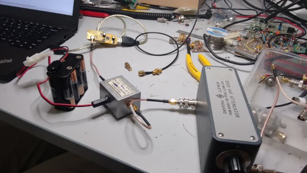
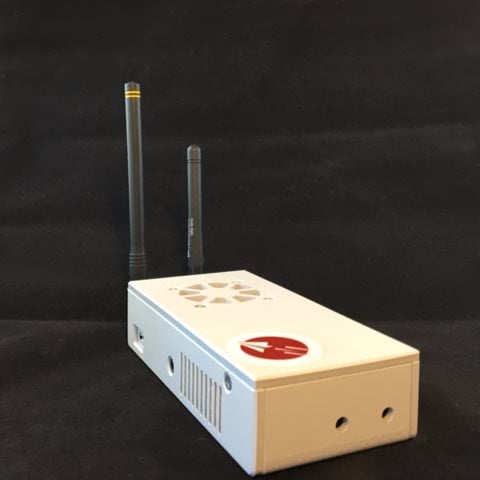
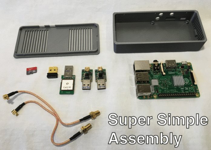
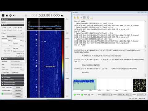
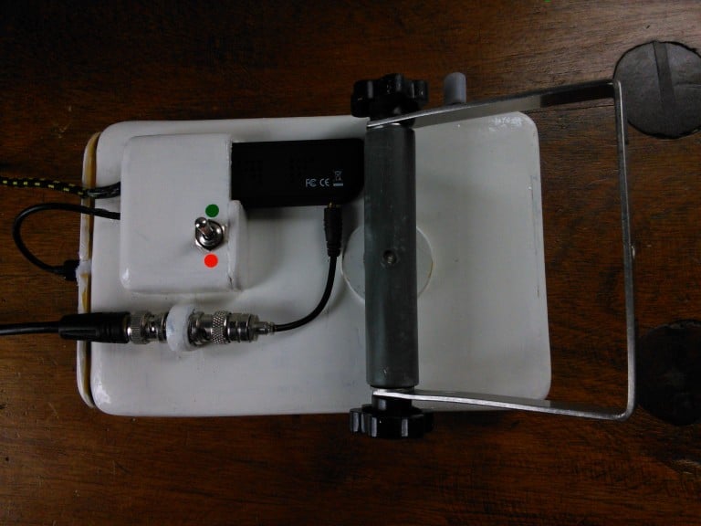
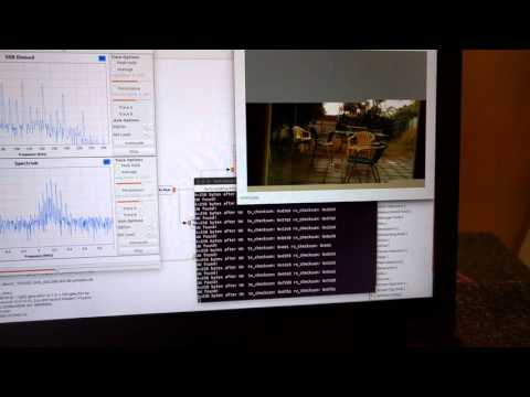
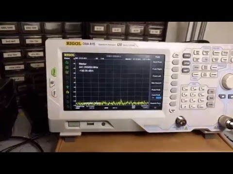
David and Mark are building a 115 kbit/s FSK SSDV (slow scan digital video) data system for high altitude balloons. In their system, on the balloon transmit side they use a Raspberry Pi, Raspberry Pi camera and a RFM22B wireless transceiver modulator board to transmit the SSDV FSK signal. On the receive side they use an RTL-SDR dongle, low noise preamplifier and a GNU Radio program to demodulate the SSDV images. The first video below demonstrates the hardware and GNU Radio program and shows them receiving the SSDV signal. In the second video they demonstrate that the images can be received at low signal levels (-106dBm) as well, by heavily attenuating the signal.
If you are interested, all their code for the SSDV system has been uploaded to https://github.com/projecthorus/HorusHighSpeed.
While testing the RTL-SDR for use in this system they also measured the noise figure of an R820T RTL-SDR dongle. The noise figure at maximum gain comes out at around 5.6 dB. By adding a low noise amplifier they reduce the measured noise figure down to 2 dB.