Category: Digital Signals

Using an RTL-SDR and Broadcast FM Radio RDS Signals to improve WiFi Networking

The performance of WiFi networks can depend heavily on how crowded the WiFi channels are in your area. For example when your neighbours start streaming a movie over their own separate WiFi network, it can cause your own WiFi connection to slow down. This happens because generally separate WiFi networks do not collaborate with one another, and when two packets are sent on the same channel at the same time, they collide causing no packets to get through.

There are several methods that attempt to stop collisions, but none are very efficient because WiFi nodes are not synchronized to one another. If each WiFi node could be synchronized to a common reference time, then avoiding collisions is made easier.

Marcel Flores, Uri Klarman, and Aleksandar Kuzmanovic from Northwestern University have been working on this idea and have come up with a system they have termed Wi-FM which is based on FM RDS signals. Many FM radio stations transmit a digital Radio Data System (RDS) subcarrier on their broadcast frequency. This RDS signal is often used to simply display information on the radio such as the station name and current song playing.

Since each nearby WiFi node should be able to receive the same RDS signal at the exact same time, it can be used as a common synchronization signal. Then once synchronized each WiFi node can listen to the other nodes and work out what their transmit scheduling is like and then optimize their own transmit schedule.

In their prototyping they used an RTL-SDR dongle connected to a PC running GNU Radio. The GNU Radio program decodes the RDS signal and the resulting information is sent to the Linux kernel which handles the WiFi transmit schedule processing.

This story was also covered on Hackaday.

WiFM radio processing path.

An RTL-SDR Based Smartwatch for Detecting Objects Touched by the Wearer

Disney Research have just released a paper describing an RTL-SDR based smart watch that they've developed a proof of concept for. The smart watch is unique in that it can be used to actually detect the exact object that the wearer is touching. 

The prototype watch does this by using the RTL-SDR to detect the electromagnetic (EM) noise emitted by particular objects and compare it against a stored database. They call this technology EM-Sense. In the paper the authors summarize:

Most everyday electrical and electromechanical objects emit small amounts of electromagnetic (EM) noise during regular operation. When a user makes physical contact with such an object, this EM signal propagates through the user, owing to the conductivity of the human body. By modifying a small, low-cost, software-defined radio, we can detect and classify these signals in real-time, enabling robust on-touch object detection. Unlike prior work, our approach requires no instrumentation of objects or the environment; our sensor is self-contained and can be worn unobtrusively on the body. We call our technique EM-Sense and built a proof-of concept smartwatch implementation. Our studies show that discrimination between dozens of objects is feasible, independent of wearer, time and local environment.

The frequencies required for EM detection are around 0 - 1 MHz which falls outside the range of the RTL-SDR's lowest frequency of 24 MHz. To get around this, they ran the RTL-SDR in direct sampling mode. The RTL-SDR is connected to the watch, but a Nexus 5 smartphone is used to handle the USB processing which streams the signal data over WiFi to a laptop that handles the signal processing and live classification. In the future they hope to use a more advanced SDR solution, but the RTL-SDR has given them the proof of concept needed at a very low cost.

An example use scenario of the watch that Disney suggests is as follows:

Home – At home, Julia wakes up and gets ready for another productive day at work. Her EM-Sense-capable smartwatch informs and augments her activities throughout the day. For instance, when Julia grabs her electric toothbrush, EMSense automatically starts a timer. When she steps on a scale, a scrollable history of her weight is displayed on her smartwatch automatically. Down in the kitchen, EM-Sense detects patterns of appliance touches, such as the refrigerator and the stove. From this and the time of day, EM-Sense infers that Julia is cooking breakfast and fetches the morning news, which can be played from her smartwatch. 

Fixed Structures – When Julia arrives at the office, EMSense detects when she grasps the handle of her office door. She is then notified about imminent calendar events and waiting messages: "You have 12 messages and a meeting in 8 minutes". Julia then leaves a reminder – tagged to the door handle – to be played at the end of the day: “Don’t forget to pick up milk on the way home.” 

Workshop – In the workshop, EM-Sense assists Julia in her fabrication project. First, Julia checks the remaining time of a 3D print by touching anywhere on the print bed – “five minutes left” – perfect timing to finish a complementary wood base. Next, Julia uses a Dremel to cut a piece of wood. EM Sense detects the tool and displays its rotatory speed on the smartwatch screen. If it knows the task, it can even recommend the ideal speed. Similarly, as Julia uses other tools in the workshop, a tutorial displayed on the smartwatch automatically advances. Finally, the 3D print is done and the finished pieces are fitted together.

Office – Back at her desk, Julia continues work on her laptop. By simply touching the trackpad, EM-Sense automatically authenticates Julia without needing a password. Later in the day, Julia meets with a colleague to work on a collaborative task. They use a large multitouch screen to brainstorm ideas. Their EM-Sense-capable smartwatches make it possible to know when each user makes contact with the screen. This information is then transmitted to the large touchscreen, allowing it to differentiate their touch inputs. With this, both Julia and her colleague can use distinct tools (e.g., pens with different colors); their smartwatches provide personal color selection, tools, and settings. 

Transportation – At the end of the day, Julia closes her office door and the reminder she left earlier is played back: “Don’t forget to pick up milk on the way home.” In the parking lot, Julia starts her motorcycle. EM-Sense detects her mode of transportation automatically (e.g., bus, car, bicycle) and provides her with a route overview: “You are 10 minutes from home, with light traffic”.

The EM-Sense watch detecting a door. The RTL-SDR dongle is the small square box under the watch.
EM-Sense: Touch Recognition of Uninstrumented Electrical and Electromechanical Objects

Meteor M-N1 Satellite Wakes up from the Dead

RTL-SDR.com reader Happysat recently wrote in with some news. A few days ago a weather satellite image decoding enthusiast from Argentina was waiting for a pass of the Russian Meteor M-N2 satellite when he discovered a strong LRPT signal at 137.1 MHz, even though the Meteor M-N2 satellite was not in sight yet. It turns out that the signal was coming from the old Meteor M-N1 satellite which was supposed to have been shut down in September 2014 due to several problems it had. The received signal is strong enough to produce a good black and white weather image, but because the satellite is not longer physically stable, sometimes the Earth’s curve can be seen in the images.

Recent images received from the resurrected Meteor M-N1 weather satellite.
Recent images received from the resurrected Meteor M-N1 weather satellite. The stabilization system has failed so the earth’s curve can be seen.

The exact reason as to why it is transmitting again is unknown, but it is speculated that it is due to a breakdown of the chemicals in the batteries. Last year we posted about how sometimes satellites which have been decommissioned and shut down can spontaneously begin transmitting again when their batteries undergo a chemical change due to thousands of failed recharge cycles. The chemical change allows the batteries to conduct electricity from the solar panels directly to the electronics, which on Meteor M-N1 could be reactivating the transmitters and imaging sensors. If this is what happened then the satellite will only be able to transmit during the day.

The Meteor M-N2 satellite is the currently official active satellite. It transmits weather satellite images with the LRPT protocol which can be received and decoded with an RTL-SDR dongle. We have a previous post on this showing an offline LRPT decoding tutorial and more recently a tutorial showing how to decode LRPT in real time. The same processes can now be adapted to the resurrected Meteor M-N1 satellite by choosing the 80K symbol rate option in the LRPT decoder.

Happysat who submitted this news originally writes:

A few days ago some guy in Argentina was waiting for the pass of Meteor M-N2 and on SDRSharp waterfall he did see LRPT Digital signals on 137.100MHz, but Meteor M-N2 was not in sight yet…

This relatively strong signal was coming from the defunct Meteor M-N1 satellite left out of control in September 2014 last year and was shutdown, although LRPT Transmissions in the past where very limited and sporadic.

Meteor M-N1 did suffer from many problems at this was the first Russian digital weather satellite in the M-series onboard many hardware in experimental stages.

After this report I tried also to capture some signals from Meteor M-N1 (some other amateurs already got small portions of images) but the satellite only transmits in direct sunlight, batteries are not charging any more.

Indicating maybe like the other older ‘deadsat’ some chemical reaction did occur inside the batteries so the power goes from the solar panels directly to the transmission parts.
It did happen before, mostly on older satellite’s only a unmodulated carrier is present when the sunlight conditions are optimal.

Surprisingly after I did record and process the 80K symbol rate QPSK signal from Meteor M-N1 with Vasili’s excellent QPSK Plugin a very nice image was generated!

Not only the sunlight provides power to the transmission part but also there is enough power to activate the imaging system which is quite amazing!

Visible channels 1-2-3 are fully working but the image is only Black and White Calibaration of the sensor are not okay so no color images can be created.

Nevertheless its a very nice addition for current LRPT weather amateurs and a big surprise its even working better when nobody controls it 😉

Because the stabilisation system failed there is no proper correction to orientate the camera and on some passes one can see the earths curve!

There are some conflicting reports about the status of Meteor M-N1 found on the internet:

Status Inactive
Details on Status (as available)

  • MSU-MR was functional with limitations (calibration issues and higher noise level in the IR channels).
  • MTVZA-GY instrument was functional with limitations due to failures of on-board memory and atmospheric sounding channels.
  • Severjanin instrument non-operational.
  • DCS was functional with limitations due to interferences to signals from ground sources.
  • GGAK-M was operational with significant limitations.
  • LRPT was functional with limitations due to information compression errors.
  • Finally, the stabilisation system failed on 23 September 2014 and the instruments could longer be operated.

On October 1, 2014 Meteor-M No 1 was withdrawn from operational use and transferred to the study of the chief designer. The decision on further operation of the spacecraft will be taken upon completion of the research program.

Its not clear the problems did got solved, and I ‘think’ M-N1 started a second life on his own. Time will tell how long the satelitte will function.

Some details:

https://directory.eoportal.org/web/eoportal/satellite-missions/m/meteor-m-1

http://planet.iitp.ru/english/spacecraft/meteor-m-n1_eng.htm

The Meteor M-N1 Satellite.
A color image received on Meteor M-N1. Colors may not be perfect.  Submitted by Jan.
A color image received on Meteor M-N1. Colors may not be perfect. Submitted by Jan.

Watching ATSC TV with an SDRplay SDR and GNU Radio

ATSC is the digital HD TV standard used within the United States and Canada. It is 6 MHz wide so the RTL-SDR with its maximum bandwidth of about 2.8 MHz cannot decode this signal. However, higher end SDR’s such as the SDRplay, Airspy and HackRF have larger bandwidths that can easy cover 6 MHz.

One SDRplay owner was able to figure out a way to decode ATSC by using a decoder written in GNU Radio. With the process the author used we note that other wide band SDR’s such as the Airspy and HackRF should also be capable of achieving the same results.

The process the author used was to first record a RAW IQ WAV file in HDSDR in Windows, making sure that any DC spike correction is applied. The WAV file is then opened in a premade GNU Radio flow graph in Linux and processed into an MPEG file. The process is not real time. The authors article shows a step by step tutorial on how its done.

In an update post to his results the author also notes that to successfully do a recording at the maximum SDRplay bandwidth of 8 MHz a RAM disk or perhaps SSD is required so that samples are not dropped.

An ATSC signal shown in HDSDR received with an SDRplay

SDR-J Now Compatible with the Raspberry Pi 2

The popular software DAB (Digital Audio Broadcast) decoder SDR-J has recently been updated and can now run on the Raspberry Pi 2. In addition the author has also added experimental DRM decoding capabilities to his shortwave receiving software. The author writes about the Raspberry Pi 2:

The Raspberry PI 2 has a processor chip with 4 computing cores. By carefully spreading the computational load of the handling of DAB over these cores it is possible to run the DAB software on the Raspberry PI 2.

In my home situation the – headless – Raspberry PI 2 is located on the attic and remotely controlled through an SSH connection using the home WiFi on my laptop in my “lazy chair”. To accomodate listening remotely, the DAB software on the Raspberry PI 2 sends – if so configured – the generated PCI samples (rate 48000) also to an internet port (port 100240). On the laptop then runs a very simple piece of program reading the stream and sending it to the soundcard

DAB is a digital audio protocol that is used in some countries as a digital alternative to broadcast FM (music stations). SDR-J is a suite of programs that includes the ability to decode DAB, FM, and several shortwave modes such as AM, USB, LSB, PSK, RTTY, WeatherFax, SSTV, BPSK, QPSK, CW, NavTex (Amtor-B), MFSK, Domino, Olivia, Hell, Throb and now DRM. It can directly connect to RTL-SDR receivers as well as other hardware such as the Airspy and SDRplay.

Screenshot of SDR-J running on the Raspberry Pi 2.

Hacking GSM Signals with an RTL-SDR and Topguw

The ability to hack some GSM signals has been around for some time now, but the steps to reproduce the hack have been long and difficult to set up. Recently RTL-SDR.com reader Bastien wrote into us to let us know about his recently released project called Topguw. Bastien's Topguw is a Linux based program that helps piece together all the steps required in the GSM hacking process. Although the steps are simplified, you will still need some knowledge of how GSM works, have installed Airprobe and Kraken, and you'll also need a 2TB rainbow table which keeps the barrier to this hack still quite high. Bastien writes about his software:

So like I said my software can "crack" SMS and call over GSM network.

How ?

I put quotation marks in crack because my software is not enough to deciphered GSM itself. My software can make some steps of the known-plaintext attack, introduce by Karsten Nohl, and by the way, increase the time to decipher an SMS or call. I'll not explain here all the steps because they are long and tedious, but there is a lot of work done behind the Gui.

Actually my software can extract Keystream (or try to find some of them) from a capture file of GSM, or by sniffing GSM with a rtl-sdr device. Then you just have to use Kraken to crack the key and you're able to decipher sms or call.

Why ?

This hack is very interesting! With only a little receiver (rtl-sdr) and some hard-disk capacity (2Tb), everyone can try to hack the GSM. It's very low cost compare to other hack vector. Moreover the success rate is really great if you guess the Keystream correctly. So when I started to done this with my hands I though -> why don't try to make something to do this automatically.
This is how Topguw was born.

Topguw, I hope, will sensitize people about risk they take by calling or sending sms with GSM.

My software is currently in beta version but I did run several time and I got good results. Maybe better than something done by hand. But Topguw is made to help people who want to learn the hack. This is why several files are made to help GSM reverse-engineering.

Topguw can be downloaded from GitHub at https://github.com/bastienjalbert/topguw. Bastien has also uploaded a video showing his software in action. If you're interested in Bastiens YouTube channel as he plans to upload another video soon where he shows himself hacking his own GSM sms/call signals.

Topguw Proof of concept - GSM Hacking educational purpose

Of course remember that hacking into GSM signals is very illegal and if you do this then you must check the legality of doing so in your country and only receive your own messages or messages that are intended for you.

Update 27 Feb 2023: Note that this content is constantly being censored by video upload sites. If the above video is down, Bastien has uploaded links to alternative video upload sites on pastebin.

Receiving Digital Amateur TV from the ISS with an RTL-SDR

The international space station (ISS) is currently testing transmission of a DVB-S digital video signal. At the moment only a blank test pattern is transmitted, but one day they hope to be able to transmit live video properly for the purposes of making live contact with astronauts, and possibly to stream video of scientific experiments, extravehicular activities, docking operations, or simply live views of the Earth from space.

Over at www.pabr.org the author Pabr has been experimenting with using an RTL-SDR dongle for the reception of these digital amateur TV (DATV) signals. Over on Reddit he also posted some extra information about his work:

I have been able to receive DVB-S broadcasts from the ISS (known as HamVideo or HamTV) with a high-gain 2.4 GHz WiFi antenna ($50), a custom downconverter ($65), a R820T2 dongle, and a software demodulator (Edmund Tse’s gr-dvb). I used to think this could only be done with much more expensive SDR hardware.

It is commonly known that rtl-sdr dongles do not have enough bandwidth to capture mainstream satellite TV broadcasts, but the ISS happens to transmit DVB-S at only 2Msymbols/s in QPSK with FEC=1/2, which translates to 2 MHz of RF bandwidth (2.7 MHz including roll-off).

Before anyone gets too excited I should mention that:

  • This was done during a favourable pass of the ISS (elevation 85°)
  • With a fixed antenna, only a few seconds worth of signal can be captured
  • Demodulation is not real-time (on my low-end PC)
  • Currently the ISS only transmits a blank test pattern.

I now believe the BoM will be less than $50 by the time the ISS begins broadcasting interesting stuff on that channel.

Pabr uses a 2.4 GHz parabolic WiFi antenna to receive the signal. He writes that ideally a motorized antenna tracker would be used with this antenna to track the ISS through the sky. Also since the DATV signal is transmitted at around 2.4 GHz, a downconverter is required to convert the received frequency into one that is receivable with the RTL-SDR. The DATV decoder is available on Linux and requires GNU Radio.

Receiving DATV from the ISS
Receiving DATV from the ISS with an RTL-SDR

Reverse engineering a wireless thermostat with an RTL-SDR

When Tom Taylors home heating boiler was replaced the builders also replaced the old wired rotary thermostat with a digital wireless one. It sounds good, but Tom soon discovered that the thermostat UI was terrible and that the buttons were horrible to press, making him prefer to shiver in the cold. So Tom decided to see if there was a smarter way to control the heating.

When Tom investigated the thermostat, he discovered that the wireless unit transmitted in the unlicensed 433 MHz band and that the thermostat only transmitted two commands, turn on or turn off. By using his RTL-SDR and the CubicSDR software on his Mac he was able to detect the short blip of the thermostat wireless signal. Next he recorded the on and off signals and opened the sound files in Audacity, an audio processing software tool. In Audacity he was able to compare the sound waveforms of the on and off signals.

From his analysis he discovered that each signal consisted of a preamble and then an on or off command which is repeated twice, presumably to reduce the likelihood of interference. Tom also discovered that the commands were encoded with pulse width modulation.

From this knowledge Tom was then able to use a cheap 433 MHz transmitter together with an Arduino microcontroller board and a short script to create identical on or off transmissions that control the boiler. Tom writes that his next steps are now to create a heating schedule based on his families shared calender, make a thermostat control loop and create a web connected interface with a Raspberry Pi.

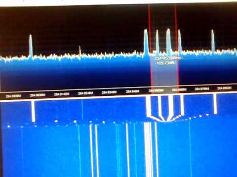
The 433 MHz thermostat on/off signal detected with an RTL-SDR in the CubicSDR software