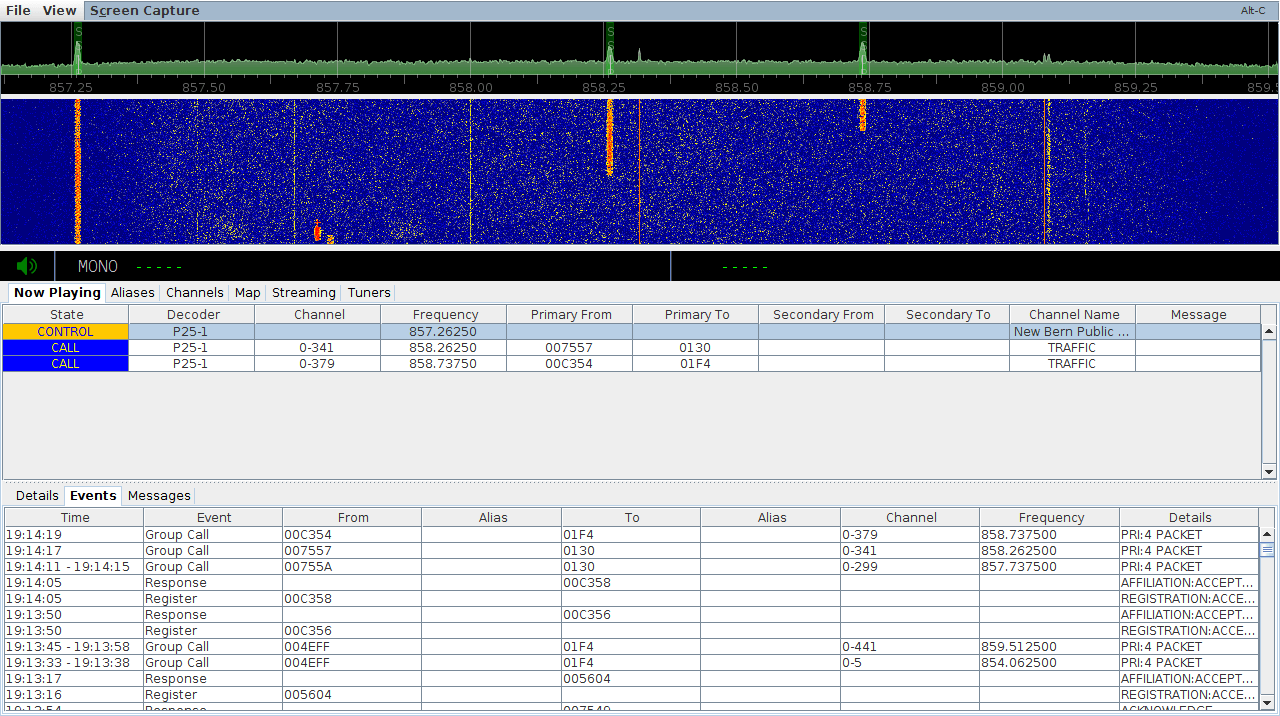
SDRTrunk is a cross platform Java based piece of software that can be used for following trunked radio conversations. In addition to trunk tracking it also has a built in P25 Phase 1 decoder. Compared to Unitrunker SDRTrunk is an all-in-one package, and currently it supports most trunking system control channels, but unlike Unitrunker it still misses out on some systems EDACS and DMR.
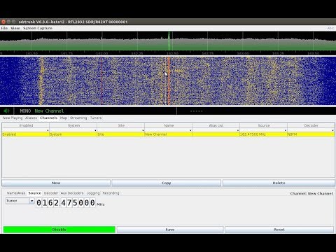
Over on his YouTube channel AVT Marketing has uploaded an excellent 6-part video series that shows how to install SDRTrunk and the Java runtime environment on Ubuntu Linux. The sections covered include, installing Java, setting the Java environment variables, installing other SDRTrunk prerequisites such as Apache Ant and the JMBE audio codec for decoding P25, and finally actually using and setting up SDRTrunk. Like all of AVT’s other videos, this is an excellent tutorial that takes you through the entire process from the very beginning so is useful for beginners as well.
If you’re new to trunking: Trunking systems are typically used with handheld radio systems (e.g. those that police, security guards, workmen etc carry around). The basic idea is that each radio constantly listens to a digital control channel which tells it what frequency to switch to if a call is being made. This allows the frequency spectrum to be shared, instead of designating one fixed frequency per user which would be very inefficient. But this system makes it difficult for scanner radios to listen in to, because the voice frequency could change at any time. Therefore software like Unitrunker and SDRTrunk which can decode the control channel is required. In addition many new systems use digital audio like P25 or DMR which requires digital decoders like SDRTrunk or DSDPlus.
![[EN subs] ISS SSTV Event Juli 2017 - Empfang von drinnen und V-Dipole](https://www.rtl-sdr.com/wp-content/plugins/wp-youtube-lyte/lyteCache.php?origThumbUrl=https%3A%2F%2Fi.ytimg.com%2Fvi%2FSTmvu34O610%2F0.jpg)